Are Magnetic Field Lines Real?
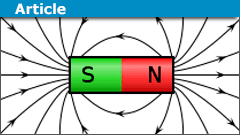
We recently had a question in the relativity forums that mentioned the behavior of magnetic field lines and reminded me of my own confusion at school about what magnetic field lines actually were. You see a lot of diagrams showing the field around a magnet that looks like this:
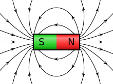
[Image source – author: Geek3, GNU Free Documentation License]
Back in my school days, it was never clear to me what these diagrams actually showed. Intuitively, it seemed to me that the magnetic field wasn’t just a bunch of discrete lines, suggesting that this is just a picture. Yet if you scatter iron filings around a magnet you do get lines, suggesting that field lines are very real. So what is going on?
Table of Contents
What are field lines?
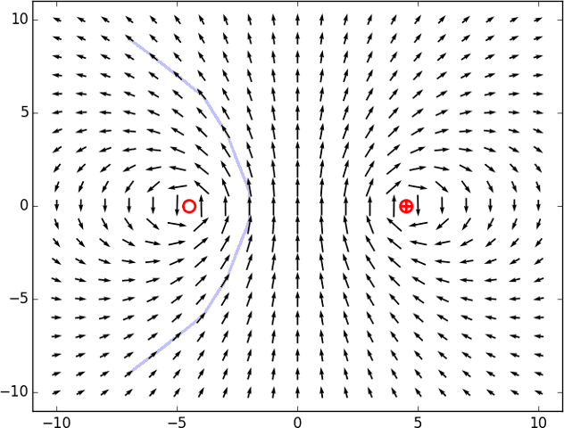
Fields that only have a single value at a point (like the air temperature) are called scalar fields. They are relatively easy to represent using contour lines, or color maps, or out-and-out 3d models in some cases. But a magnetic field is a vector field, meaning that it has both a strength and a direction at every point. This is harder to draw, but there are several approaches. Possibly the most honest way is to show the direction and strength of the field as an arrow at each point (or on a regular grid of points, at least). For example, a circular loop of wire with a current running through it generates a magnetic field. Taking a plane passing through the diameter of the current loop, the magnetic field looks like this:

The red circles show where the current loop passes into and out of the plane of the screen. Each arrow shows the strength (by its length) and direction (by, well, its direction) of the magnetic field at the point at the middle of the arrow. Note that I was careful to pick a slice where all of the arrows would lie in that slice, so these 2d arrows are enough. If I had picked an off-center slice I’d have needed to represent the arrows coming out of the screen somehow – not impossible to draw, but harder.
But a problem with such diagrams is that the length of the arrows is constrained by the distance to their neighbor, so if you have a field strength that varies strongly, you can find that the arrows shrink so small you can’t see the direction. In fact, the picture above shows the log of the field strength rather than the field strength itself, for exactly this reason. You can, of course, just make all the arrows the same length – but then you lose information about the field strength. Or you can let arrows overlap – but this can easily end up in a hard-to-understand mess.
One possible solution is to try joining up arrows. Start with one arrow, and connect it to the arrow it points to. Connect that arrow to the arrow it points to, and so on. Here’s a sketch of that:
You can see that this is a rather inaccurate approach because the arrows don’t necessarily quite point to any nearby one. It gets better if you make the grid finer, so there are more arrows and you’re more likely to find a nearby arrow that is being pointed at. And if you go to an infinitely fine grid (i.e., an arrow at every point, just like the magnetic field is defined at every point) then any arrow always points directly to an infinitesimally nearby one. Infinite numbers of arrows are hard to draw, but for this we invented calculus. Connecting infinite numbers of infinitely small arrows gives us an integral curve of the field – also known as a field line. Getting a numerical integrator to do this for the current loop gives this familiar-looking diagram:
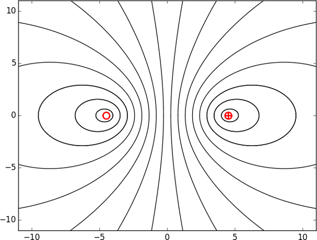
So that’s what field lines are. The magnetic field (or any vector field) has a strength and a direction at every point in space. If you pick a starting point and just “go with the flow” of the field, the path you follow is a field line. Like contour lines, they only show particular parts of the field. But unlike contour lines, they don’t mark 1equal magnetic field strength. We could draw such contours by joining up points that have arrows of equal length, and they would, in general, be a different shape to the field lines.
Are field lines real?
So, back to my original confusion. Is the magnetic field really a bunch of lines, like the ones you get by scattering iron filings?
No, a magnetic field is not a discrete bunch of lines. The most true-to-life representation of the magnetic field is, in my opinion, the arrow diagram. The field isn’t really arrows with a spatial extent, nor is it discrete like that. But the diagram gives you a sense that there is a strength and a direction at every point, and shows you the overall pattern of the field.
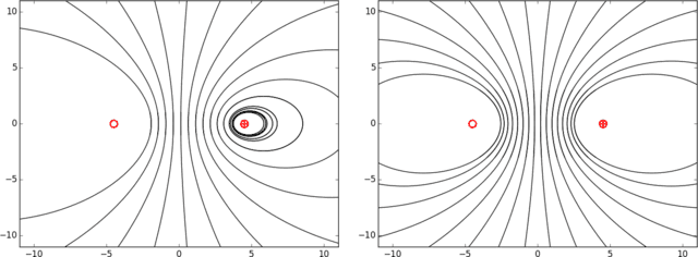
But sometimes the arrows aren’t the most helpful way of representing the field, and the field line depiction becomes useful. Field lines are real in the same sense that the arrows are, or the contour lines on a map. They aren’t just a picture – they genuinely represent something mathematical about the field. But the field lines I choose to draw aren’t unique. The picture above results from choosing a few points evenly spread across a diameter of the wire loop as the “seeds” of the lines, and I chose these because of symmetry concerns – all the lines must pass through the loop, and I expect some kind of symmetry about this line because the wire itself has symmetry here. If instead, I make a poor choice of seed points then the resulting picture may have areas without field lines, or an asymmetrical distribution – like these two examples:
But what about those iron filings?
So, if I am saying that the magnetic field most definitely is not a bunch of discrete lines, why do iron filings trace them out?
This is an example of self-organizing behavior. Drop a single iron filing near a magnet and it will tend to line up with the direction of the magnetic field vector at that point. Iron “conducts” magnetic fields, slightly strengthening the field along its axis, while weakening the field beside it. So the next filing to fall nearby is pulled into line by the slightly distorted magnetic field near the first filing. Lining a lot of little filings up in the direction the field points is very similar to the procedure I used to draw field lines – this is just a “natural” way to do it.
In fact, if you look carefully at an image of iron filings in a magnetic field (e.g. at Wikipedia), you will see the lines are often broken and “skip” sideways where there weren’t enough filings for the self-organization to happen perfectly. And the distribution clearly doesn’t mirror symmetric as it should be. So, although iron filings do appear to show magnetic field lines, it’s because they change the magnetic field to cause that behavior.
Solar Flares
In the comments to this article, anorlunda pointed out another situation often described as something related to magnetic field lines – solar flares. The dynamics of magnetic fields in plasma are way beyond my knowledge, and the fact that they interact with the free charged particles making up the plasma makes it a very complicated topic. However, I can say this. Flares and coronal mass ejections are driven by the magnetic fields in the plasma but, once again, they don’t simply trace out magnetic field lines.
Summary
Field lines are the integral curves of a vector field, the lines one creates by picking a point and repeatedly aligning oneself to the direction of the field at that point then stepping an infinitesimal distance in that direction. They are no more real than the contour lines on a map are real – they represent some aspects of reality, but they are not the whole story. Iron filings pick out magnetic field lines as a result of the way they reshape the magnetic field, in a form of self-organization, not because the field lines are really all there is to magnetic fields.
References
Simple Analytic Expressions for the Magnetic Field of a Circular Current Loop, Simpson, Lane, Immer, Youngquist, https://ntrs.nasa.gov/archive/nasa/casi.ntrs.nasa.gov/20010038494.pdf


Ferrofluid is a nice way to demonstrate self-organization and emergent complexity
http://www.physicscentral.com/explore/action/ferrofluids.cfm
View attachment 235633 View attachment 235634Yes, Ferrofluids are fine for viewing magnetism. However, you will not see field lines in a bulk, dense liquid, only spiking from Rosensweig Instabilities.
The SPIONS react quite differently when they are only 1% of the solution and the other 99% is carrier fluid.
When dispersed evenly and sealed within a airless environment, you see this: View attachment 238897
Artificial Magnetic Black Hole created with a cylinder magnet pole facing rear of Ferrolens with 9 each of Red, Green, Blue and White 3mm LED's around the outer circumference of the lens, facing into the center.
Comments?
More on this project here on RG: https://www.researchgate.net/project/Artificial-Black-Holes-of-Electromagnetic-Fields
OP states magnetic field line is not real. Even not real I wonder magnetic field or force line is indispensable in getting magnetic flux density B where flux of magnetic field line is taken.
The lines reflect one important bit of reality: a magnetic object (e.g. an iron filing) released into a magnetic field will move along the field line where it was released. There's a bit of vector math, involving field gradients and the induced dipole in the filing, but it all works out to "following the field lines". They indicate the direction of the force that the field exerts on a magnetic dipole.
I just call it simply a Flux Gate. A Begin to the Flux Gate, and a End to the Gate.
I know Flux Gate Refers to something Else Entirely its just a Term I call it I made for it. As The Flux that is in its like Stasis mode trajectory
I know when you add the Iron Filings it shows… These Flux lines but thats not the case. And those are Generic becuase the magnet itself has strength irregularities
And I so so laugh when my Magnet Im checking its strength and My magnet Sticks to the phoooooone.
Becuase My My cell phone has good apps for reading that gauss. And its funny becuase my phone dosnt really mind like 3000 gauss. Im like oooh. I hope this dosnt damage my phone when that happens.
I really Think its Funny when you Hold a magnet of 3000 guass Say and set a half inch from AC Adaptor plug box thing! It begins to vibrate when hold magnet its funny…can really feel the vibrations and frequencyy
I think he was imagining the magnetic field to be something that trails around the wire like Earth's atmosphere follows it through space. That (wildly incorrect) model makes sense of his insistence that field lines must be moving. So I think an animated version of the arrow diagram, showing the arrows rotating and scaling as the wire moves through, might have helped. It would show the field as a thing that's always there, just disturbed by the wire moving through it (more like a boat's wake than a planet's atmosphere). The arrows are, for me, the closest thing to an honest depiction of the way Maxwell's equations model the magnetic field.
Also possibly an animated demo of field lines around a moving wire might help. You could use different seed point strategies to make different movies. For example, if the wire runs in the z direction and is moving in the x direction, a set of seed points along the y axis would produce concentric circles that shrink as the wire approaches the y axis and grow as it moves past and away. Seed points along the x axis would produce a set of shrinking circles from points ahead of the wire and expanding ones from points behind the wire. And seed points that moved along with the wire would indeed produce circles that moved along with the wire. Maybe the fact that you can create such different movies just by making different choices, and pointing out that the field lines are actually connecting different arrows in each frame so are in some sense different entities in each frame, might help.
In the original thread "moving-charge-in-a-magnetic-field-problem" the OP was convinced that those magnetic field lines moved along with the source. A few of us tried to convince him that, as the source moved, the field changed in strength at any particular point, but didn't have a "velocity" of it's own. Can you come up with a better way to get this point across?
This is a response video made specifically to this blog post … I don't think the dipole force of a magnet can be really understood using black and white "maps"
If you do it the other way around I think that should just result in mirroring the dimension going in/out.There may be a bit of subjectivity going on here depending on the post-processing in the brain. But when I cross my eyes inward, I am able to lock the two images together pretty easily — but the fused image seems to have almost no depth.
When I focus beyond the screen, it's more of an effort to get the images to fuse at first, but when I do succeed, it has more depth and realism. There is one loop, just a little clockwise from the upper-right diagonal, that seems to pop right out of the screen and arc through the space between me and the screen. The same loop in the "other version" looks much flatter, as if I'm looking at a 3D scene where a 2D photograph is suspended in the air, perhaps somewhere behind the computer screen.
Interesting. It works for me crossing my eyes inward, and that's the effect I was aiming for. It's possible I messed up creating it, of course! I think the video does the job better, so I shan't try to regenerate it.If you do it the other way around I think that should just result in mirroring the dimension going in/out.
At first I found it hard to see the 3D shape, even though I have a fair amount of practice viewing this kind of thing. But I realized that I was crossing my eyes inwards rather than outwards.Interesting. It works for me crossing my eyes inward, and that's the effect I was aiming for. It's possible I messed up creating it, of course! I think the video does the job better, so I shan't try to regenerate it.
Ferrofluid is a nice way to demonstrate self-organization and emergent complexity
http://www.physicscentral.com/explore/action/ferrofluids.cfm
View attachment 235633 View attachment 235634
Or a stereogram. If you can kind of cross your eyes until the red wire loops overlap you get a kind of lame 3d effect.
View attachment 234991At first I found it hard to see the 3D shape, even though I have a fair amount of practice viewing this kind of thing. But I realized that I was crossing my eyes inwards rather than outwards. There are two ways of aligning the right and left image, and we need to select the way that the designer intended. Once I lined up my eyes to look behind the screen, I was able to see the lines running through space, including one big loop that seems to arc out of the screen towards you.
I don't think you need to explain the plasma, but just mention that you're excluding plasma from the article. BTW, plasma lines cross each other, whereas the kinds of magnetic lines you wrote about can never cross; an important property.
Great Insight, but the Wikipedia link is broken :frown:I believe I've addressed both of these now – added a paragraph on solar flares and linked directly to the image on Wikipedia instead of its details page.
Great Insight, but the Wikipedia link is broken :frown:That's weird – it works if you "open link in new tab", but not if you just click on it. I tried to link to the page with all the file information instead of the image itself, but maybe Wiki doesn't like that? I'll investigate later.
Great Insight, but the Wikipedia link is broken :frown:
Great insight @Ibix !
I don't think I know enough about solar plasma physics to follow your suggestion.I don't think you need to explain the plasma, but just mention that you're excluding plasma from the article. BTW, plasma lines cross each other, whereas the kinds of magnetic lines you wrote about can never cross; an important property.
Great Insight, and helpful to dispel misconceptions. :thumbup:Thanks!
You can expand the article.I don't think I know enough about solar plasma physics to follow your suggestion. I agree it would be a good subject, since I see your point about prominences potentially giving the impression of flowing along field lines. I just don't think I know enough to do it.
If you know of an appropriate source, happy to link it.
Great Insight, and helpful to dispel misconceptions. :thumbup:
You can expand the article. I think it would be helpful to mention plasmas such as solar prominences where wiki says "the prominence plasma flows along a tangled and twisted structure of magnetic fields generated by the sun’s internal dynamo." Also in the news is magnetic reconnection where the lines twist and cross themselves. Those things don't invalidate what you wrote, but they are a more complicated case where the lines are more than just magnetic, and which can lead laymen to think all magnetic lines are real.
It's often said as a rule of thumb that the "line density" relates to the strength of the field.I agree this can only be a rule of thumb, because there are specific counter examples where the contours of magnetic field strength are different shapes from the magnetic field lines (a wire moving perpendicular to its length, for example). And there are cases where the field line density is completely a matter of choice (a stationary wire produces concentric circular field lines – the density is trivially related to the density of seed points).
But there is an element of truth for things like the wire loop (or any permanent magnet). The field lines all pass through the loop (through the magnet), so it makes sense to pick seed points in the finite region where all lines pass. But those lines sweep back around through the infinite outside region and they must space out. I can pick a finite uniformly spaced set of points in the loop, but that cannot correspond to uniform spacing in the infinite region outside – the spacing must grow with distance. So the spacing grows with falling field strength.
So I think it's a rule limited to situations where there's a finite region that all field lines pass through. And it's not independent of the choice of seed points (see the left hand "bad choice of seed point" diagram in the insight). And it's definitely not true in detail. But there's some truth to it.
Also, can this be seen with iron filings too? I've seen some images that suggest so, others that don'tYou mean, can you see field lines being more spread out with the iron filings? No, because there is an infinite set of possible field lines. The density effect only works if you pick systematically placed seed points in a finite region where all field lines pass.
However, there are two points to be aware of. First, far from the magnet the field is weak and there's little to drive the self-organisation. So you see fewer lines because there's less strength in the order-imposing process. Secondly, it's not independent of the density of iron filings. If you dump all the filings on top of the magnet so only a few happen to bounce to regions far away, again you won't see many lines. And iron filings are attracted to the magnet, so the density will almost certainly be higher near the magnet unless you're careful to control it. So I'd guess that's why you have this "sometimes you see it, sometimes you don't" feeling. You need to control for filing density variations.
I do have a question. It's often said as a rule of thumb that the "line density" relates to the strength of the field. However, I don't unterstand the immediate connection between "longer arrows" and "lines closer together", especially since those properties are in some sense "perpendicular" to each other.
Also, can this be seen with iron filings too? I've seen some images that suggest so, others that don't.
@Ibix I would say at least partly successful. It might work better for a cylindrical magnet than it does for a current loop. In any case, it does illustrate the point that the 3-D model is necessary to get the proper divergence of the flux lines, i.e. where density falls off as 1/r^2 from a point source, etc.It's surprisingly non-painful to create a YouTube video. It really needs to be watched in fullscreen mode because the field lines are too fine otherwise.
Half a million "likes" by next Tuesday for this one, you reckon?
Be sure to link to your Insight in that thread :smile:The thread I had in mind was this one: https://www.physicsforums.com/threads/moving-charge-in-a-magnetic-field-problem.958010/ Unfortunately it's locked and the OP got banned for something else the other day. :rolleyes: But if someone with appropriate permissions thinks a link is appropriate and wants to add one, please go ahead.
That sounded like a challenge. :wink:
View attachment 234989
It's a bit of a mess. I think it may need some animation for you to be able to sort out the field lines clearly, but I don't have time right now to figure out how to do that.@Ibix I would say at least partly successful. It might work better for a cylindrical magnet than it does for a current loop. In any case, it does illustrate the point that the 3-D model is necessary to get the proper divergence of the flux lines, i.e. where density falls off as 1/r^2 from a point source, etc.
If we're both thinking about the same thread, the problem is something I kind of illustrated with the "bad choices of seed points".Be sure to link to your Insight in that thread :smile:
I think it may need some animation for you to be able to sort out the field lines clearly, but I don't have time right now to figure out how to do that.Or a stereogram. If you can kind of cross your eyes until the red wire loops overlap you get a kind of lame 3d effect.
View attachment 234991
Thanks. @Ibix . There's been some real madness on the forums about this lately, and I think it stems from people taking the iron filling example to mean much more than it actually does.If we're both thinking about the same thread, the problem is something I kind of illustrated with the "bad choices of seed points". You could, indeed, represent the field lines around a moving wire as "moving along with the wire" by picking seed points for the field lines that moved along with the wire – but it's fairly obvious that you are drawing different field lines if you explicitly note that you need to move your seed points. If you used fixed seed points while the wire moves, the field lines just expand. The field lines change over time if the current is changing with time is, I think, the only safe statement of that kind that can be made.
I do have one question. You said "[f]ield lines are the integral curves of a vector field." Can that sentence be translated into a path integral of some sort?I don't think so, although I'm open to correction. My understanding is that a path integral of some (not necessarily vector) field is its integral along a chosen path, while integral curves require the field to have a notion of direction and they let the field define the path. So if you walk through a rainstorm, how wet you get depends on the integral of the flow rate along the path you choose to walk – that's a path integral. But there's no sense of direction in a rainstorm, unless we go and look at the velocity field of the drops. Integral curves of that field would be the paths traced out by the drops as they fall.
Hope that makes sense.
It may be worth mentioning that field lines drawn on a two dimensional piece of paper really don't work very well, because the line density for a source that radiates from a point need to fall off as inverse square, but on a 2-D piece of paper the line density falls off as 1/r. It is a much more accurate representation of actual field lines=they would be quite exact, if they were made out of wire on a 3-D model.That sounded like a challenge. :wink:
View attachment 234989
It's a bit of a mess. I think it may need some animation for you to be able to sort out the field lines clearly, but I don't have time right now to figure out how to do that.
Thanks. @Ibix . There's been some real madness on the forums about this lately, and I think it stems from people taking the iron filling example to mean much more than it actually does.
I do have one question. You said "[f]ield lines are the integral curves of a vector field." Can that sentence be translated into a path integral of some sort?
kn
@Ibix A very interesting article=thank you. :smile: It may be worth mentioning that field lines drawn on a two dimensional piece of paper really don't work very well, because the line density for a source that radiates from a point need to fall off as inverse square, but on a 2-D piece of paper the line density falls off as 1/r. It is a much more accurate representation of actual field lines=they would be quite exact, if they were made out of wire on a 3-D model. Then, the line density would fall off as 1/r^2 away from a point source like they should. ## \ ## Edit: Note: This is the case with magnetic field lines , where the sources can be considered to be "poles" that obey the inverse square law. (There are also current sources with magnetic fields, but that generally does not complicate matters in regard to the flux lines). In regions where there are no sources, ## nabla cdot B=0 ## is obeyed, analogous to the electrostatic ## nabla cdot E=0 ##. For both magnetic and electric field lines, the above comments of the 2-D sketch vs. 3-D model apply.