AC Circuit Phasors: Find I1, I2, I3

In summary: Read moreIn summary, the conversation is about a problem involving alternating current and finding the phasors as complex numbers. The given data includes voltage, frequency, and resistances and capacitances of various components in the circuit. The conversation includes calculations using Ohm's Law and Kirchoff's Law, as well as peer review of the results. There are discussions about equations and potential errors in the calculations, but ultimately, the results are agreed upon with some rounding errors.
  • #1
Martin Harris
103
6
Homework Statement
AC Circuit Phasors
Relevant Equations
Kirchoff's and Ohm's Law
Summary:: Hi, I tried attempting this problem in alternating current in order to find out the phasors as complex numbers, and I would be more than grateful if someone could peer review it, and confirm my calculations (Please see below both the Figure and the calculations)

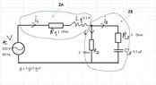
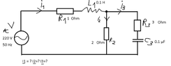
Please find attached the electrical circuit as a figure.

Given data:
Voltage V220 V
Frequency50 Hz
Resistance R11 Ω
Coil electrical inductance L10.1 H
Resistance R22 Ω
Resistance R33 Ω
Capacitor electrical capacitance C30.1 μF = 10-7 F
I1, I2, I3 =? (Phasors as complex numbers for alternating current)
From Ohm's Law:
$$I = \frac V Z (Eq1)$$where I = current, V= Voltage and Z = impedance
From Kirchoff's Law:
$$I=I1=I2+I3 (Eq2)$$
Given that branches containing R2 and R3 with C3 are in | | (parallel), then:
$$V2=V3$$
and
$$\frac{1}{Z}= \frac{1}{Z_1}+\frac{1}{Z_2} (Eq3)$$
$$Z_1=R1+iωL = R1 + i*2π*F*L (Ω)$$ where i is the imaginary part of the impedance
$$Z_1=1Ω + (2*π* 50Hz *0.1H* i) Ω $$
$$ Z1 = (1+31.41592 i)Ω $$
$$Z2=R2=2Ω$$
(Z2 just 2Ω since it's just the resistance, it won't appear as a complex number impedance)
$$Z3 = R3-ixC3 = 3 Ω-\frac{1}{2*π*F*C} = 3 Ω-\frac{1}{2*π*50Hz*10^-7 F}i Ω $$
$$Z3 = (3 - 31830.988i) Ω$$
From Eq3:
$$\frac{1}{Z}= \frac{1}{(1+31.41592 i)Ω}+\frac{1}{2Ω} $$
According to Microsoft MathSovler
$$Z=(1.987950624+0.126177045i) Ω $$

$$From Eq1: I1 = I = \frac V Z $$
$$I= \frac {220V} {(1.987950624+0.126177045i)Ω} $$
$$I1= (110.276245603−6.992857044i)A $$
$$ From Eq2 (Kirchoff's Law): I2=I1-I3 = (110.276245603−6.992857044i)A - I3 (Eq4) $$
$$ V2=V3$$ hence $$I2*Z2=I3*Z3 (Eq5)$$
Substituting Eq4 into Eq5 yields:
$$(110.276245603−6.992857044i)A * 2Ω = I3 * (3 - 31830.988i) Ω$$
Solving for I3 (According to Microsoft Math Solver)
$$I3 = (0.000440024+0.006928817i) A $$
Now from Eq5 we can solve for I2 =I1-I3
$$I2=(110.276245603−6.992857044i)A - (0.000440024+0.006928817i) A$$
$$I2 = (110.27576−6.999728 i)A$$

I am really confused why I3 is so low though, for sure I did something wrong because I3 has negative value both on the real and imaginary part.

I would be more than grateful if someone could check my work as a peer review.
 

Attachments

  • Circuit.PNG
    Circuit.PNG
    8.3 KB · Views: 100
Last edited:
  • Like
Likes Delta2
Physics news on Phys.org
  • #2
The imaginary part of Z3 has the wrong sign. I didn't check the magnitude.
 
  • Like
Likes Martin Harris
  • #3
Gordianus said:
The imaginary part of Z3 has the wrong sign. I didn't check the magnitude.
Hi
Thanks for your reply, I looked again at it
I assumed $$Z3 = R3 (resistance real part) + iXC3 (imaginary part of the impedance)$$
so $$Z3 = 3 Ω + i*(\frac {1} {2*π*50Hz*10^-7F })Ω$$
$$Z3=(3Ω+i*(\frac {1} {π*0.00001})Ω)$$, right?
 
Last edited:
  • #4
The modulus of the capacitive reactance Is OK. However, the imaginary unit should carry a negative sign.
 
  • Like
Likes Martin Harris
  • #5
Gordianus said:
The modulus of the capacitive reactance Is OK. However, the imaginary unit should carry a negative sign.
Right I understood, thanks for that, well spoted! Perhaps I carried on the sign from the coil over to the capacitor, so the coil should be +ve and the capacitor -ve.

By having $$Z3=R3-iXC3$$

And $$ I = I1 =I2+I3 $$

I get:
$$I= I1 = (110.276245603−6.992857044i)A $$
$$I3 = (0.000440024+0.006928817i) A $$
$$I2 = (110.27576−6.999728i) A$$

Now I am confused because I3 seems tiny...whilst I1 and I2 seem huge compared to I3...

I got no idea if these values are even correct, not sure if the work I did is correct though
 
Last edited:
  • #6
No wonder I3 Is small. The modulus of Z3 Is quite large compared with Z1 and Z2.
 
  • Like
Likes Martin Harris
  • #7
Gordianus said:
No wonder I3 Is small. The modulus of Z3 Is quite large compared with Z1 and Z2.
Yes, you're right.
What can you tell about the values on I1 and I2? Do they make any sense? I'm not sure if values for I1 and I2 are right though...
 
  • #8
I'm using my phone and checking complex math with a small screen isn't simple.
I suggest checking the results with KCL and KVL.
 
  • #9
Yes, well I used KCL to get I2=I1-I3, having calculated I=I1=V/Z and I3 from I2Z2=I3Z3
My general Z was calculated as 1/Z = 1/Z1+1/Z2
 
  • #10
I've been following this thread with my phone and I can hardly read it. When I get back home I'll check the numbers.
 
  • #11
I just checked with a big screen. Eq 3 is wrong. Look at the circuit.
 
  • #12
First you forgot part ZA by considering Z=ZB only.
Second in my opinion Z[=ZB]=1.99999998026079-0.000125663703042964i
 

Attachments

  • Physics Help 10_10_21.jpg
    Physics Help 10_10_21.jpg
    27.6 KB · Views: 94
  • Like
Likes Martin Harris
  • #13
Gordianus said:
I just checked with a big screen. Eq 3 is wrong. Look at the circuit.
You're absolutely right, now I did:
$$ Z_overall = Z1 + \frac {Z2*Z3} {Z2+Z3}$$
Then
$$ I = I1 = \frac {V} {Z_overall} =\frac {220} {(2.99999998+31.415794336i)} $$
Final results:
$$I1=(0.662682446−6.939565186i)A$$
$$I2=(0.662246414−6.939606755i)A$$
$$I3 =(0.000436032+0.000041569i)A$$
 
Last edited:
  • #14
I agree with the result, but there are some rounding errors.

Z1 = R1 + XL1 = ( +1.000000000000 +31.415926535898 j ) ohm;
Z2 = R2 + 0 = ( +2.000000000000 +0.000000000000 j ) ohm;
Z3 = R3 + XC1 = ( +3.000000000000 -31830.988618379070 j ) ohm;

Z23 = Z2 // Z3 = ( +1.999999980261 -0.000125663703 j ) ohm;
Z123 = Z1 + Z23 = ( +2.999999980261 +31.415800872195 j ) ohm;

Vin = Vrms = ( +220.000000000000 +0.000000000000 j ) volt;
I1 = Vin / Z123 = ( +0.662682172378 -6.939563768654 j ) amp;
V23 = I1 * Z23 = ( +1.324492280395 -13.879210675423 j ) volt;

I1 = Vin / Z123 = ( +0.662682172378 -6.939563768654 j ) amp;
I2 = V23 / Z2 = ( +0.662246140197 -6.939605337712 j ) amp;
I3 = V23 / Z3 = ( +0.000436032181 +0.000041569057 j ) amp;
 
  • Like
Likes Martin Harris and Babadag
  • #15
Please, be lenient with this comment.
Where can I buy a 15 digit voltmeter?
 
  • #16
Gordianus said:
Where can I buy a 15 digit voltmeter?
You don't need to. Just simulate it with double precision.
Different approaches lead to different numerical stability and rounding patterns.
You can write a ladder network as a continued fraction.
Attenuators attenuate the differences.
Amplifiers amplify the differences.
 
  • #17
Gordianus said:
Please, be lenient with this comment.
Our results agreed to only six digits, I would have expected much better numerical agreement.

There must be a reason why we differ. After a bit of detective work …

For reactance evaluation I used Pi = 4 * Atn(1) = 3.141592653589793
The value of Pi used to evaluate post #13 was; 3.141592000000000
That now perfectly explains all our numerical differences.

I am numerically happy.
 
  • Like
Likes Martin Harris
  • #18
Baluncore said:
I agree with the result, but there are some rounding errors.

Z1 = R1 + XL1 = ( +1.000000000000 +31.415926535898 j ) ohm;
Z2 = R2 + 0 = ( +2.000000000000 +0.000000000000 j ) ohm;
Z3 = R3 + XC1 = ( +3.000000000000 -31830.988618379070 j ) ohm;

Z23 = Z2 // Z3 = ( +1.999999980261 -0.000125663703 j ) ohm;
Z123 = Z1 + Z23 = ( +2.999999980261 +31.415800872195 j ) ohm;

Vin = Vrms = ( +220.000000000000 +0.000000000000 j ) volt;
I1 = Vin / Z123 = ( +0.662682172378 -6.939563768654 j ) amp;
V23 = I1 * Z23 = ( +1.324492280395 -13.879210675423 j ) volt;

I1 = Vin / Z123 = ( +0.662682172378 -6.939563768654 j ) amp;
I2 = V23 / Z2 = ( +0.662246140197 -6.939605337712 j ) amp;
I3 = V23 / Z3 = ( +0.000436032181 +0.000041569057 j ) amp;
Hi
Just a question, how do we know 220V is the rms though? I was just given 220V and thought that's the peak value
 
  • #19
Martin Harris said:
Hi
Just a question, how do we know 220V is the rms though? I was just given 220V and thought that's the peak value
The international mains voltage is now about 230 Vrms = 325 Vpeak.
Like you, SPICE assumes a 220 V sinewave oscillates between ±220 V = 220 Vpeak.

Since it was not specified otherwise, I assumed that the 220 V was most likely to be Vrms.
The currents I computed are therefore also RMS.

The computation of VA power and VAR differ for Vrms and Vpeak.
 
  • Like
Likes Martin Harris
  • #20
Baluncore said:
The international mains voltage is now about 230 Vrms = 325 Vpeak.
Like you, SPICE assumes a 220 V sinewave oscillates between ±220 V = 220 Vpeak.

Since it was not specified otherwise, I assumed that the 220 V was most likely to be Vrms.
The currents I computed are therefore also RMS.

The computation of VA power and VAR differ for Vrms and Vpeak.
Hi
Thanks a lot for the quick reply! It is much appreciated.
Please find attached the SPICE simulation results for 220V and 311V
are also peak. I was just given 220V though.
Now, I'm confused, am I doing something wrong? Because I assumed 220V is peak and hence the currents

What voltage should I put into SPICE Simulation then? 220V or 311V? Since I want to correlate the simulation with the manual calculations. I'm confused now if the currents calculated by manual work are peak or rms.
 

Attachments

  • 220V.PNG
    220V.PNG
    13.5 KB · Views: 86
  • 311V.PNG
    311V.PNG
    13.6 KB · Views: 88
  • 220VandCurrents.PNG
    220VandCurrents.PNG
    17.9 KB · Views: 91
  • 311VandCurrents.PNG
    311VandCurrents.PNG
    18.5 KB · Views: 97
  • #21
Martin Harris said:
What voltage should I put into SPICE Simulation then? 220V or 311V?
A physicist or mathematician might assume; V = 220;
An engineer or technician might assume; V = 220 Vrms * √2;

Martin Harris said:
I'm confused now if the currents calculated by manual work are peak or rms.
It really does not matter which you used. They all stay the same.
If it is not specified, make a decision, state it clearly, then stick to it.

Only if you will evaluate power do you need to know if it is Vrms or Vpk.
The integration of instantaneous (v*i) over a full cycle will give you real power.

If you avoid the integration;
The product of Vrms and in-phase current, Irms.real, will give real power.
The product of Vpk and Ipk.real requires a factor of ½ to give real power.
 
  • Like
Likes Martin Harris
  • #22
Baluncore said:
A physicist or mathematician might assume; V = 220;
An engineer or technician might assume; V = 220 Vrms * √2;It really does not matter which you used. They all stay the same.
If it is not specified, make a decision, state it clearly, then stick to it.

Only if you will evaluate power do you need to know if it is Vrms or Vpk.
The integration of instantaneous (v*i) over a full cycle will give you real power.

If you avoid the integration;
The product of Vrms and in-phase current, Irms.real, will give real power.
The product of Vpk and Ipk.real requires a factor of ½ to give real power.
Thanks a lot! I understood!
Now I'm trying to figure out why I1 roughly = I2 and I3 is so small
I think becauseso little current is shunted to the R3C3, hence I2 roughly = I1
Little current I3 because capacitor C3 = 0.1 micro Farad

I mean, what makes it that I3 is so small, hence I1=I2?
From Kirchoff's Law, I1=I2+I3
I3 is small due to Z3, hence I2 has to be roughly I1
 
Last edited:
  • #23
Martin Harris said:
I mean, what makes it that I3 is so small, hence I2=I3?
From Kirchoff's Law, I1=I2+I3
I3 is small due to Z3, hence I2 has to be roughly I1
I think you mean, I3 is small, hence I1 ≈ I2.

I3 is small because C1 is small, 0μ1 F.
At 50 Hz, XC1 is huge = -31k831 ohm.

I3 is also lower than you might expect because;
the voltage across Z3 is lowered by the presence of XL1.
XL1 = +31.41 ohm, which is big compared to the 1 ohm of real series resistance in Z1.
 
  • Like
Likes Martin Harris
  • #24
Baluncore said:
I think you mean, I3 is small, hence I1 ≈ I2.

I3 is small because C1 is small, 0μ1 F.
At 50 Hz, XC1 is huge = -31k831 ohm.

I3 is also lower than you might expect because;
the voltage across Z3 is lowered by the presence of XL1.
XL1 = +31.41 ohm, which is big compared to the 1 ohm of real series resistance in Z1.
Thanks a lot! Yeah, sorry about that, I was thinking of Kirchoff's Law already when I was typing it, so please consider it a typo.

For V2=V3=V23 I got 14V, as I did the magnitude, seems about right I guess (?)
 
  • #25
Martin Harris said:
For V2=V3=V23 I got 14V, as I did the magnitude, seems about right I guess (?)
V23 = I1 * Z23 = ( +1.324492280395 -13.879210675423 j ) volt;
V23 mag = 13.9422655 V, phase = -84.548775°.
 
  • Like
Likes Martin Harris
  • #26
Baluncore said:
V23 = I1 * Z23 = ( +1.324492280395 -13.879210675423 j ) volt;
V23 mag = 13.9422655 V, phase = -84.548775°.
Yeah, I just rounded it to 14V, but you're more precise! Thanks a lot! By the way how did you get that phase?
I got phase around -80°
 
  • #27
Martin Harris said:
By the way how did you get that phase?
Given complex V23 = ( +1.324492280395 -13.879210675423 j ) volt;

Function Amplit( Byval a As complex ) As Double
Return Sqr( a.real * a.real + a.imag * a.imag )
End Function

Function Phase( Byval a As complex ) As Double
Return Atan2( a.imag, a.real )
End Function
Then convert radians to deg.
 
  • Like
Likes Martin Harris

1. What is an AC circuit phasor?

An AC circuit phasor is a representation of a sinusoidal voltage or current in an alternating current (AC) circuit. It is a complex number that includes both magnitude and phase information.

2. How do you find the values of I1, I2, and I3 in an AC circuit?

To find the values of I1, I2, and I3 in an AC circuit, you can use Kirchhoff's current law (KCL) and Ohm's law. KCL states that the sum of currents entering a node must equal the sum of currents leaving the node. Ohm's law states that the current in a circuit is equal to the voltage divided by the resistance. By applying these laws to the circuit, you can solve for the values of I1, I2, and I3.

3. What is the purpose of using phasors in AC circuits?

Phasors are used in AC circuits to simplify the analysis of complex sinusoidal signals. By converting the time-domain representation of a signal into a phasor, you can use algebraic operations to analyze the circuit, rather than dealing with complex trigonometric functions.

4. How do you convert between phasor and time-domain representations?

To convert between phasor and time-domain representations, you can use Euler's formula, which relates complex numbers to trigonometric functions. By using this formula, you can convert between the magnitude and phase of a phasor and the amplitude and phase of a sinusoidal signal.

5. Can phasors be used for non-sinusoidal signals?

No, phasors are only applicable to sinusoidal signals. Non-sinusoidal signals have complex frequency spectra and cannot be represented by a single phasor. However, phasors can be used to analyze the individual sinusoidal components of a non-sinusoidal signal.

Similar threads

  • Engineering and Comp Sci Homework Help
Replies
6
Views
1K
  • Engineering and Comp Sci Homework Help
Replies
8
Views
2K
  • Engineering and Comp Sci Homework Help
Replies
21
Views
2K
  • Engineering and Comp Sci Homework Help
Replies
25
Views
3K
  • Introductory Physics Homework Help
Replies
22
Views
2K
  • Engineering and Comp Sci Homework Help
Replies
2
Views
2K
  • Introductory Physics Homework Help
Replies
10
Views
1K
  • Introductory Physics Homework Help
Replies
1
Views
1K
  • Engineering and Comp Sci Homework Help
Replies
10
Views
4K
  • Engineering and Comp Sci Homework Help
Replies
4
Views
2K
Back
Top