Amplitude of Analog Filter Question

In summary, the answer is that you need to divide an imaginary by a complex to get the correct impedance.
  • #1
nao113
68
13
Homework Statement
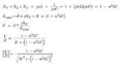
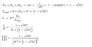
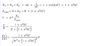
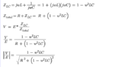
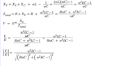
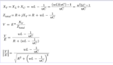
Calculate V/E of the circuit below. I tried to calculate this one, is it correct? Thank you
Relevant Equations
Vc = 1/jwC
Question
Screen Shot 2022-06-01 at 17.49.43.png

Answer;
Screen Shot 2022-06-01 at 17.49.25.png
 
Physics news on Phys.org
  • #2
That does not look right to me.
You have a potential divider.
Reactance; Xv = XL + XC;
But what is the sign of XC ?
Impedance; Ztotal = R + jXv
The output V = E * jXv / Ztotal
 
  • #3
Baluncore said:
That does not look right to me.
You have a potential divider.
Reactance; Xv = XL + XC;
But what is the sign of XC ?
Impedance; Ztotal = R + jXv
The output V = E * jXv / Ztotal
How about this one?
 

Attachments

  • Screen Shot 2022-06-01 at 19.48.03.png
    Screen Shot 2022-06-01 at 19.48.03.png
    11 KB · Views: 85
  • #4
2nd guessing will not educate you, nor solve the problem.
At the frequency where L and C are resonant, there will be a deep notch with V = 0.
How can XL + XC = 0 ?
 
  • #5
Baluncore said:
2nd guessing will not educate you, nor solve the problem.
At the frequency where L and C are resonant, there will be a deep notch with V = 0.
How can XL + XC = 0 ?
thank you for the feedback, what do you mean by 2nd guessing? for `How can XL + XC = 0 ?` what should I do for that question? Did I got it wrong for my calculation?
 
  • #6
What is the reactance XL of an inductor?
What is the reactance XC of a capacitor?
 
  • #7
Baluncore said:
What is the reactance XL of an inductor?
What is the reactance XC of a capacitor?
based on my class, here it is
 

Attachments

  • Screen Shot 2022-06-01 at 20.27.22.png
    Screen Shot 2022-06-01 at 20.27.22.png
    14.9 KB · Views: 78
  • #11
Both XL and XC are imaginary. R is real.
So XL + jXC does not equal Xv. Both XL and XC lie on the same axis.
Xv = ωL - 1/ωC
Then you fail to divide.
 
  • #12
Then, I remove the imaginary, how about it?
 

Attachments

  • Screen Shot 2022-06-01 at 20.58.22.png
    Screen Shot 2022-06-01 at 20.58.22.png
    10.4 KB · Views: 79
  • #13
You must move more methodically and accurately.
You removed the j, but immediately ignored the negative sign, then forgot to divide.
 
  • #14
Baluncore said:
You must move more methodically and accurately.
You removed the j, but immediately ignored the negative sign, then forgot to divide.
how about this? I am sorry, I am new in this area so kinda confused
 

Attachments

  • Screen Shot 2022-06-01 at 21.25.14.png
    Screen Shot 2022-06-01 at 21.25.14.png
    9.8 KB · Views: 74
  • #15
I wouldn't multiply XL by j, and then divide XC by j . That does not seem fair.
Z = R + j X;
If you work on the reactance, X only, you can ignore j for the moment.
You are having problems with fractions.
X = ωL - 1 / ωC = ( ωC·ωL - 1 ) / ωC .
 
  • #16
I am so sorry, I didn't realize it
I revised again
 

Attachments

  • Screen Shot 2022-06-01 at 22.00.31.png
    Screen Shot 2022-06-01 at 22.00.31.png
    13.4 KB · Views: 80
  • #17
Resistance, real, is plotted along the x-axis, reactance, imaginary, is on the y-axis. Impedance is a point on the map, represented by a complex number. Below the x-axis is negative, so it is a capacitive reactance, above the x-axis is inductive reactance. Resonance lies on the x-axis, where reactance is zero.

You must introduce j when you write a complex impedance, because it keeps the orthogonal real and imaginary axes apart. Z = R + jX is prevented from becoming Z = R + X by the presence of j.

So in your second line you must carefully identify the reactance components with j .
 
  • #18
Screen Shot 2022-06-01 at 22.16.54.png

is it? do I need to change plus to minus after R in Z total? Then for |V/E|, did I put quadrat and roots correctly? should. I also put root on the top?
 
  • #19
Now you are going to need to propagate that R + j ( ) along the second line;
That is needed to keep the impedance orthogonal.
 
  • #20
Baluncore said:
Now you are going to need to propagate that R + j ( ) along the second line;
That is needed to keep the impedance orthogonal.i
how about this? is this what you mean as propagate?
 

Attachments

  • Screen Shot 2022-06-01 at 22.54.33.png
    Screen Shot 2022-06-01 at 22.54.33.png
    10.1 KB · Views: 77
  • #22
Baluncore said:
I think you need to brush up on your complex arithmetic.
https://en.wikipedia.org/wiki/Complex_number

V = E * ( 0 + j Xv ) / ( R + j Xv )
So you need to divide an imaginary by a complex.
Thank you very much, I see, I think my answer is still not correct. I ll try to learn your suggestion.
 

1. What is the amplitude of an analog filter?

The amplitude of an analog filter refers to the magnitude or strength of the signal passing through the filter. It is a measure of how much the filter affects the amplitude of the input signal.

2. How is the amplitude of an analog filter measured?

The amplitude of an analog filter is typically measured in decibels (dB), which is a logarithmic unit of measurement. It is calculated by taking the ratio of the output amplitude to the input amplitude and then converting it to a logarithmic scale.

3. What factors affect the amplitude of an analog filter?

The amplitude of an analog filter can be affected by several factors, including the filter's frequency response, the type of filter (e.g. low-pass, high-pass, band-pass), the cutoff frequency, and the order of the filter. Additionally, the components used in the filter's design can also impact its amplitude.

4. How does the amplitude of an analog filter affect the output signal?

The amplitude of an analog filter can attenuate or amplify the input signal, depending on the frequency and characteristics of the filter. For example, a low-pass filter will attenuate high-frequency signals, while a high-pass filter will attenuate low-frequency signals. The amplitude of the output signal will also depend on the filter's gain and the input signal's amplitude.

5. Can the amplitude of an analog filter be adjusted?

Yes, the amplitude of an analog filter can be adjusted by changing the filter's parameters, such as the cutoff frequency or the filter's gain. It can also be adjusted by adding or removing components in the filter's design. However, it is important to note that changing the amplitude of a filter can also affect its other characteristics, such as its phase response and frequency response.

Similar threads

  • Engineering and Comp Sci Homework Help
Replies
8
Views
856
  • Engineering and Comp Sci Homework Help
Replies
2
Views
1K
  • Engineering and Comp Sci Homework Help
Replies
2
Views
847
  • Engineering and Comp Sci Homework Help
Replies
27
Views
2K
  • Engineering and Comp Sci Homework Help
Replies
16
Views
960
  • Engineering and Comp Sci Homework Help
Replies
16
Views
2K
  • Engineering and Comp Sci Homework Help
Replies
3
Views
867
  • Engineering and Comp Sci Homework Help
Replies
3
Views
892
  • Engineering and Comp Sci Homework Help
Replies
1
Views
808
  • Engineering and Comp Sci Homework Help
Replies
8
Views
4K
Back
Top