CRT gun "dissection" questions

  • Thread starter artis
  • Start date
  • Tags
    Crt Gun
In summary: The filaments need amps, control grid signals need less than 1 mA. Metal with same thermal expansion coefficient as glass is resistive, so pins must be paralleled for filaments.Now a couple of questions...1) Why are all other accelerator grids connected to a single pin but the filament box is connected with two wires that extend as 3 pins through the glass , why use so many pins for just one small attachment? To allow more current , if so why is that important ?2) The 3 separate wires not connected to anything else each going inside each separate filament, are they the 1st accelerator grid connection to each filament that are controlled by the video amplifier with which it can control each color gun beam intensity at
  • #1
artis
1,481
976
While messing around with old tv's I had a Panasonic sent the innards to recycling but at the factory kept some souvenirs , broke off the electron gun from the tube (that sweet swoosh sound when the air rushes to fill the vacuum).
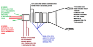
So long story short I know the basics of how an electron gun works but some questions arose upon closer inspection of the gun itself. I made a drawing representing the grids from the filament side up to the end of the gun.
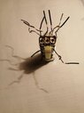
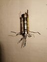
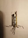
Also made some (not that great) pictures of the real thing.

Now what I found bit interesting is that for example. The box housing the filaments themselves which I suppose is at ground potential (minus) has two parallel connections, one at either side. One of the connections extends through the glass as a single pin while the other connection on the other side extends through the glass as two pins, so a total of 3 pins are used all of whom are parallel.
Meanwhile all the other accelerator grids further on are connected parallel in pairs and each pair have just a single pin extending through the glass.
The last grid is not connected to any of the tube pins instead has 3 metallic sticks that once inside the tube touch the inner conductive coating of the tube which is electrically connected to the anode.

Then there are 2 wire with 2 pins that supply the heating current to all 3 filaments in parallel.
And then there are 3 separate pins with 3 separate wires going in the middle of each filament but not electrically connected to any other part.Now a couple of questions

1) Why are all other accelerator grids connected to a single pin but the filament box is connected with two wires that extend as 3 pins through the glass , why use so many pins for just one small attachment? To allow more current , if so why is that important ?2) The 3 separate wires not connected to anything else each going inside each separate filament, are they the 1st accelerator grid connection to each filament that are controlled by the video amplifier with which it can control each color gun beam intensity at each instant as the combined beam sweeps the horizontal pixel lines?
If so I suppose these 1st grids are the only ones whose voltage gets varied over time as the voltage on the further grids is fixed with respect to time?3) As for the accelerator grids, why are they connected like that, for example, the 1st and 3rd are connected together with the 2nd in between the two connected to the lower down the line grids? I always thought you would want each next grid to have a more positive potential to increase acceleration.
Also why are the last grids , namely , 2nd, 4th, 5th, and 6th all connected together? I can't quite understand why would you want multiple grids one after the other at the same potential , how does that help?

Please see attached files.
 

Attachments

  • CRT gun.png
    CRT gun.png
    25.9 KB · Views: 91
  • crt gun 1 (3).jpg
    crt gun 1 (3).jpg
    20.3 KB · Views: 84
  • crt gun 1 (5).jpg
    crt gun 1 (5).jpg
    22.2 KB · Views: 81
  • crt gun 1 (6).jpg
    crt gun 1 (6).jpg
    21.5 KB · Views: 94
Engineering news on Phys.org
  • #2
1. Filaments need amps, control grid signals need less than 1 mA. Metal with same thermal expansion coefficient as glass is resistive, so pins must be paralleled for filaments.

2. Three independent control grids, voltage relative to the cathode box.

3. Acceleration grids must also do electron optics. They focus the three beams onto the phosphor dots. Look at the electron exit from the cathode box. Is it the same shape as a screen stripe, so electrons will be projected to the far screen.

The end electrode appears to be the anode. As electrons exit that electrode they enter an electric field-free space. The end electrode contacts the aquadag inside the glass envelope, which is connected to the many +kV anode supply.
https://en.wikipedia.org/wiki/Aquadag#Use_in_cathode_ray_tubes
 
  • Informative
Likes Klystron and sophiecentaur
  • #3
Baluncore said:
Filaments need amps, control grid signals need less than 1 mA. Metal with same thermal expansion coefficient as glass is resistive, so pins must be paralleled for filaments.
Yes I know that tube filaments tend to need low voltage current but I did some checking with ohmmeter, the 3 filaments themselves are all connected parallel with a total resistance of around 5 ohms. they are connected to two small busbars to which the output pins are connected. There are just 2 output pins for the filaments.
The 3 pins that I talked about which are all connected to the cathode box are just connected to the cathode box and the cathode box is not electrically connected to the filaments nor is it connected to the first accelerator grids individual for each filament.
Could it be that the electron beam current that is emitted from the filaments and accelerated by the grids, that some of that beam current strikes the cathode box and the connection to it are in order to bleed that extra negative charge away ?

The filaments themselves as said have just two pins for all 3 filaments and that's it.Now I wonder, as the video amplifier controls the voltages on each of the 3 individual small accelerator grids packed inside the cathode box, say that one of the guns is shut off for a while the grid turned negative, what happens with the thermionic emission of the electrons from the filament , the filament itself doesn't stop glowing. Are electrons still emitted during this moment, and if so where do they go?
 
  • #4
I think you are making an assumption that the filament is emitting electrons when it is not. What you describe as the cathode box is the actual cathode and is the only thing emitting electrons of any substantial amount. It's what is known as an indirectly heated cathode.
 
  • #5
Your essay was written, based on your first observations, that are themselves based on your earlier partial understanding. The pictures do not show the cathode, the control grid, nor the filaments.

We have insufficient information to be more precise. There seems to be nothing to discuss or explain.
The TV make and model, the CRT part number, and the circuit diagram would help.
 
  • #6
Generally, the AquaDAG* coating collects stray internal signals and such from the CRT electronics; also serving as the electron return path following phosphor screen activation in many CRT designs.

Some textbooks and manuals compare the aquadag layers to a filter capacitor. I visualize it more as the shell on a nut but protecting the exterior from the 'hot' interior. Despite coatings, nearly every CRT and monitor I tested leaked EM; though primarily in uncoated directions.


*Though proprietary the term has common usage in electronics.
 
Last edited:
  • #7
artis said:
the video amplifier controls the voltages on each of the 3 individual small accelerator grids packed inside the cathode box,
Those 'grids' in the 'cathode box' are actually the cathodes of the three electron guns, where the video is applied at around 100Vp-p.

The grids themselves are where the beam shaping, focus, and astigmatism correction are done. These are service adjustments done with potentiometers (pots) by the service technician when a CRT is replaced or when some component drifts with age upsetting the viewing.

Hope this helps!

Cheers,
Tom
 
  • Informative
Likes Klystron
  • #8
artis said:
... broke off the electron gun from the tube ... that sweet swoosh sound when the air rushes to fill the vacuum
IMO, this isn't a safe thing to do. I've seen these old TV picture tube implode and throw glass everywhere.
 
Last edited:
  • Like
Likes Klystron
  • #9
dlgoff said:
IMO, this isn't a safe thing to do. I've seen these old TV picture tube implode and throw glass everywhere.
Well as you are well aware I'm sure the tube has the thinnest glass as it approaches the gun and at the gun itself. Also the shape of it. Well I learned this from an old electrician who showed it to me back in the day whenever he dealt with worn out tubes.
It is safer for me to transport these tubes to the recycling factory whenever I do that with them being filled with air than as they are. Given their heavy I have dropped them almost a couple of times, so for a worn out dead tube I just break the "neck" off.
But sure glass has internal stress and the crack can travel upwards and the tube can in theory implode so I'm careful and this should not be taken as an advice. I also wear safety glasses whenever I do something like that and take other precautions.
I don't want to get this thread locked down as I am still planning to take apart the electron gun cathode carefully if I will be able to and maybe come back with some pictures and questions/answers.
 
  • #10
There is a tip one the end of the neck that is meant for this. Pull the plastic off that separates the pins and you will find it. This will safely allow the air to leak into the tube so it is safe from implosion. I had assumed when I started reading this thread that you were doing this. Any other way is asking for trouble.
 
  • Informative
  • Like
Likes Klystron, artis, berkeman and 1 other person
  • #11
Averagesupernova said:
There is a tip one the end of the neck that is meant for this. Pull the plastic off that separates the pins and you will find it. This will safely allow the air to leak into the tube so it is safe from implosion. I had assumed when I started reading this thread that you were doing this. Any other way is asking for trouble.
bold by me.

This YouTube video confirms this procedure:
 
  • Like
Likes artis
  • #12
Averagesupernova said:
There is a tip one the end of the neck that is meant for this.
Might sound as me trying to excuse my lack of information but I knew about this, in fact I think this is the end seal through which they pull the vacuum in the first place in the factory after they make the tube and then after pulling the vacuum they probably heat seal the glass in that tip.

But there is a problem, the end tip is surrounded by the metal pins for the gun. It is hard to access and I would need to brake off or mend the pins before I could get to brake it.
But the video author does it elegantly I must say.

I would note just one thing in the video, whether under vacuum or not you don't want to put a CRT in a ousehold garbage bin or near it anyway. The right thing to do is to make sure it gets to the electronics recycling factory as it needs proper recycling , back in the day most ended up together with empty milk packs and old cheese in landfills sadly
 
  • #13
Averagesupernova said:
There is a tip one the end of the neck that is meant for this. Pull the plastic off that separates the pins and you will find it. This will safely allow the air to leak into the tube so it is safe from implosion. I had assumed when I started reading this thread that you were doing this. Any other way is asking for trouble.
Since this thread involves a poentially very dangerous situation, the thread needs to be closed at this point. Thank you @Averagesupernova for the safety tip.
 
  • Sad
  • Like
Likes Tom.G, dlgoff and artis

What is a CRT gun?

A CRT gun, or cathode ray tube gun, is a device used in old television sets and computer monitors to produce a beam of electrons that creates the images on the screen.

Why would someone want to dissect a CRT gun?

Dissecting a CRT gun allows for a better understanding of how it works and the components involved. It can also be a fun and educational activity for science enthusiasts.

What tools are needed for dissecting a CRT gun?

The tools needed for dissecting a CRT gun may vary, but some common tools include a screwdriver, pliers, wire cutters, and safety goggles.

Is it safe to dissect a CRT gun?

Dissecting a CRT gun can be dangerous if proper safety precautions are not taken. It is important to wear safety goggles and work in a well-ventilated area to avoid exposure to harmful gases and particles.

What can be learned from dissecting a CRT gun?

Dissecting a CRT gun can provide insight into the inner workings of a television or computer monitor. It can also teach about the principles of electricity, magnetism, and electron beams.

Similar threads

  • Electrical Engineering
Replies
30
Views
2K
Replies
37
Views
3K
  • Electrical Engineering
2
Replies
46
Views
4K
Replies
31
Views
2K
Replies
32
Views
2K
Replies
13
Views
4K
  • Electrical Engineering
3
Replies
83
Views
4K
  • Electrical Engineering
Replies
27
Views
1K
  • Introductory Physics Homework Help
Replies
4
Views
268
  • Electromagnetism
Replies
11
Views
958
Back
Top