- #1
piepermd
- 51
- 2
- TL;DR Summary
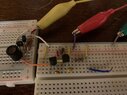
- I have an oscillator circuit for finding the resonant frequency of LC circuits. It works in LTSPICE incorporating Varactor diodes, but does not behave the same way on the breadboard.
In the circuit simulator there is no voltage at the Varactor cathodes when Vbias is zero, but depending on the Varactor I use on the breadboard it can be as high as 7.4 volts! There is minimal current through the series resistor when Vbias is applied in LTSPICE, but I always see a significant voltage drop across the series resistor for Vbias on the breadboard, indicating there is indeed current flowing. This is not supposed to happen unless the breakdown voltage is exceeded. Any ideas why the circuit does not behave as expected when built on the breadboard? I have tried this in different iterations with different breadboards and I always see the same result. I tried building a similar circuit on a perf board and still got a voltage drop across the series Vbias resistor.
Here is a JPG but I’ll try to send the file as well.

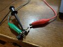
Here is a JPG but I’ll try to send the file as well.
 )
)