Integrate or divide the input impedance for transmission lines in series?

In summary, the OP wants to know equations that show interrelations of separate parts within a transmission line.
  • #1
patkood
5
0
Homework Statement
I have tried divide input impedance for transmission line based on RLGC value divided to N, and take into Zin function, but cannot go ahead.
I do not find any reference showing what is the math relation for total Zin and each parts of Zin.
to be brief:
(1) if we divide transmission line with N equal parts, we could obtain each parts of transmission line by simple divide total RLGC by N? am I correct?
(2) if I have N parts of transmission line with different length(different RLGC), how could we obtain total RLGC? can we add them together?

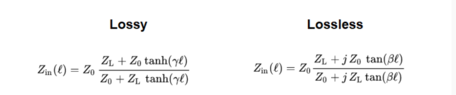
we can start with simple equation from short and open load as listed in the attached file.

Thanks very much!
Relevant Equations
total with L, Zin=Z0cot(Belta*L) ,
each part with length equal to L/N, Zin(i)= Z0*cot(Belta*L/(N^2)). i=1,2....N
Not sure if could obtain Zin=Z1+Z2+......Zn
TLs.jpg
Here I list my problem in the attachment.
 

Attachments

  • Z equation transmission Line more parts connect.pdf
    175.6 KB · Views: 82
Last edited by a moderator:
Physics news on Phys.org
  • #2
Hi. I think you are on the right path with 1). My guidance would be to find the total impedance of L0 and then divide that by Z0 which would get you N.
 
Last edited:
  • #3
osilmag said:
Hi. I think you are on the right path with 1). My guidance would be to find the total impedance of L0 and then divide that by Z0 which would get you N.
The question is not clear but I'm guessing the OP wants ##Z_{in}## for different lengths.

I'm no expert but we have (from the Post #1 attachment)$$Z_{in} = Z_0 \left( \frac {Z_L + jZ_O \tan βℓ}{Z_O + jZ_L \tan βℓ} \right)$$The relationship between input impedance and length (given all other parameters are the same) is quite complicated.$$Z_{in}(ℓ=L_0) = Z_0 \left( \frac {Z_L + jZ_O \tan βL_0}{Z_O + jZ_L \tan βL_0} \right)$$ $$Z_{in}(ℓ=\frac {L_0}N) = Z_0 \left( \frac {Z_L + jZ_O \tan β\frac {L_0}N}{Z_O + jZ_L \tan β\frac {L_0}N} \right)$$ $$Z_{in}(ℓ=NL_0) = Z_0 \left( \frac {Z_L + jZ_O \tan βNL_0}{Z_O + jZ_L \tan βNL_0} \right)$$Edited.
 
Last edited:
  • #4
Hi Osilmag and Steve4Physics,
Thanks for the help.
I re-think my problem and try to make clear below:
(1) what Steve supplied is correct, but I I would like to know more for different parts within a transmission line, for example, the total lengh L being divided by N parts, their impedance Z(i),i=1,.2..3...N is not independent, each Z(i) has its locations. So I want to find equation for Z(in) that has location variables, only become this we could integrate together to obtain total impedance for the whole line(length= L).
it may be clear to see the below table.
first row is imput impedance for three parts.
second row is supposed for equal divide of Δx.
Third row is supposed for non equal divident.
Second row and third row may have different length in total(just an example).
Z0Z1(x1)Z2(x2)Z3(x3)
location at zero point,x0=0x1=x0+Δxx2=x1+Δxx3=x2+Δx
x0=0x1=x0+Δyx2=x1+2*Δyx3=x2+3*Δy
if we integrate z0 to z3 for the second row with equal divident that seems ok.(also not sure)
if we integrate z0 to z3 for third row, that might be different:
a1) integrate z0,z1,z2,z3
a2) integrate z1,z3,z2,z0.
(2) it would be quite different to obtatin imput impedance If I place one same short connector between z1 and z2, or between z2 and z3.

so if I make clear of the equations for divided parts, I would see through total z from frequence domain to know what is wrong with my connections.(I know we could employ time domain analysis by numerical computation, but the above idea could see from RLGC to build the total transmission, and inteprete more information----problems from R,L,G,C.... )
 
  • #5
To add more, input impedance is both length and frequency dependent. so I guess if we exchange location for divided parts, we got different results in whole frequency band.
 
  • #6
Sorry to say, as I suppose we could divide and integrate the transmission lines, it is a lossy line not lossless line, so the input impedance equation would be little changed.
 

Attachments

  • lossyline.PNG
    lossyline.PNG
    7.6 KB · Views: 67
  • #7
It sounds like your asking about the Z parameters of a transmission line segment. Then you can cascade them if necessary, which, of course should give you the same answer as a longer TL. Most people use S-parameters for these, but they can all be converted to the others. There's lots of stuff on the web about TLs. Like these (chosen mostly at random, first good content method, LOL):
https://qucs.sourceforge.net/tech/node61.html
https://upcommons.upc.edu/bitstream...microwave_circuits.pdf?sequence=4&isAllowed=y
 
  • #8
Your lumped element model is just an approximation to a real TL. It gets better as you add more sections, but it's never the exact answer. Yes, you should be able to divide by N as you described.
 
  • #9
Hi DaveE,
Thanks for the reply and reference.
I still would like to know equations that show interrelations of separate parts.
As the above show divided parts as independent short transmission line.
if I suppose, there being different length of transmission line, and I connect them together to form a new transmission line.
How could I derive the equation?
Ztotal=f(Z1, Z2, Z3.....), Z1,Z2,Z3...can be determined from RLGC and length parameters.
It is important because in reality we frequenty encounter connect multiple lines together and some connections have defects or incorrect connections, I can simulate incorrect connections at various joints by employing the above equation.
It can be a good reference if we find total impedance has abnormanities.

Thanks very much!
 
  • #10
patkood said:
Hi DaveE,
Thanks for the reply and reference.
I still would like to know equations that show interrelations of separate parts.
As the above show divided parts as independent short transmission line.
if I suppose, there being different length of transmission line, and I connect them together to form a new transmission line.
How could I derive the equation?
Ztotal=f(Z1, Z2, Z3.....), Z1,Z2,Z3...can be determined from RLGC and length parameters.
It is important because in reality we frequenty encounter connect multiple lines together and some connections have defects or incorrect connections, I can simulate incorrect connections at various joints by employing the above equation.
It can be a good reference if we find total impedance has abnormanities.

Thanks very much!
I think you just have to work through the math for dissimilar lines. There will be reflections at each interface with mismatched impedances. It's kind of a mess for multiple sections, what with reflections of reflections, standing waves, etc. I'm not aware of an easy fix. I do suspect it's easier with s-parameters, but it's been so long since I did any of that I'm not sure. Either way there's no simple solution. In practice, EEs will use simulators for this.
 
  • #11
patkood said:
How could I derive the equation?
Ztotal=f(Z1, Z2, Z3.....), Z1,Z2,Z3...can be determined from RLGC and length parameters.
How about this:$$Z_{in} = Z_0 \left( \frac {Z_L + jZ_0 \tan βℓ}{Z_0 + jZ_L \tan βℓ} \right)$$Suppose we have N sections of transmssion line. The i-th section, considered in isolation with its load ##Z_{L,i}## has impedance:$$Z_{in,i} = Z_{0,i} \left( \frac {Z_{L,i} + jZ_{0,i} \tan β_i iℓ_i}{Z_{0,i} + jZ_{L,i} \tan β_i ℓ_i} \right)$$The load impedance of the i-th section is the input impedance of the sections following i-th section. We can use an iterative approach a build-up the overall value of ##Z_{in}##.

a) Calculate ##Z_{in, N}## (the input impedance for the last section).

b) Calculate ##Z_{in, N-1}## taking ##Z_{L,N-1} = Z_{in,N}## (giving the input impedance for last 2 sections).

c) Calculate ##Z_{in, N-2}## taking ##Z_{L,N-2} = Z_{in,N-1}## (giving the input impedance for last 3 sections).

etc.

Eventually you find ##Z_{in,1}## which is the required overall impedance.

Trying to combine the above steps into a single algebraic equation would be unmanageable. But for numerical calculation purposes, a simple computer program would be quite practical.

Edits: cosmetic only.
 
  • #12
patkood said:
It is important because in reality we frequenty encounter connect multiple lines together and some connections have defects or incorrect connections, I can simulate incorrect connections at various joints by employing the above equation.
It can be a good reference if we find total impedance has abnormanities.
This might be obvious, but there is a very good reason for why we do our very best to make sure all segments are as close to 50 Ohm as possible(or 75 Ohm if that is what you are using) . Yes, you can analytically handle imperfections using Z- or S-parameters but if you are in a situation where a bunch of "accidental" mismatches have a significant effect on what you are doing it is also very likely the case that the only way you will be able to understand what is going on is by actually measuring the whole line assembly using a VNA or some form of TDR, modelling is not very useful.

There are of course situation where you introduce mismatches on purpose (say in a stepped impedance filter), but typically you are then only dealing with small number of "steps" and the algebra becomes manageable. That said, if your goal is to actually design say a filter you will most likely going to be using Sonnet, HFSS or similar software.

Also, all of this of course assumes that you are dealing with a single mode....If not, it gets very, very complicated.
 
Last edited:
  • Like
Likes Joshy, DaveE and berkeman
  • #13
I definitely agree with the TDR.
 

1. What is the purpose of integrating or dividing the input impedance for transmission lines in series?

The purpose of integrating or dividing the input impedance for transmission lines in series is to determine the characteristic impedance of the transmission line. This is important in ensuring maximum power transfer and minimizing signal reflections.

2. How do you calculate the input impedance for transmission lines in series?

The input impedance for transmission lines in series can be calculated by taking the ratio of the voltage and current at the input of the transmission line. This can be done using Ohm's Law (Z = V/I) or by using the reflection coefficient formula (Γ = (ZL - Z0)/(ZL + Z0)), where ZL is the load impedance and Z0 is the characteristic impedance of the transmission line.

3. What is the difference between integrating and dividing the input impedance for transmission lines in series?

Integrating and dividing the input impedance for transmission lines in series are two different methods used to calculate the characteristic impedance. Integrating involves finding the total impedance of the transmission line by adding the individual impedances of each segment, while dividing involves finding the average impedance of the transmission line by dividing the total impedance by the number of segments.

4. Why is the input impedance of transmission lines in series important?

The input impedance of transmission lines in series is important because it affects the performance of the transmission line. If the input impedance is not properly matched to the load impedance, there will be signal reflections and loss of power, resulting in poor signal quality. Matching the input impedance ensures maximum power transfer and minimizes signal reflections.

5. What factors can affect the input impedance of transmission lines in series?

The input impedance of transmission lines in series can be affected by various factors such as the length and cross-sectional area of the transmission line, the dielectric constant of the material used, and the frequency of the signal being transmitted. These factors can impact the characteristic impedance and must be taken into consideration when designing and using transmission lines.

Similar threads

  • Engineering and Comp Sci Homework Help
Replies
3
Views
2K
  • Engineering and Comp Sci Homework Help
Replies
7
Views
1K
  • Engineering and Comp Sci Homework Help
Replies
2
Views
2K
  • Engineering and Comp Sci Homework Help
Replies
2
Views
1K
  • Engineering and Comp Sci Homework Help
Replies
32
Views
2K
  • Engineering and Comp Sci Homework Help
Replies
1
Views
1K
  • Engineering and Comp Sci Homework Help
Replies
18
Views
2K
  • Engineering and Comp Sci Homework Help
Replies
1
Views
1K
  • Electrical Engineering
Replies
5
Views
2K
  • Engineering and Comp Sci Homework Help
Replies
2
Views
1K
Back
Top