philns
- 4
- 2
- TL;DR
- For a project I'm starting now, I'd need to convert a circular motion generated from an electric motor into a loop shaped as , through any combination of gears, leverages or mechanical intermediation . So that at a certain level, one fix point on any of those gear would draw an 8 shaped loop. Then defining which elements defines the sizes of the 8 shape. Finally that point should possibly be always on top of any other mechanical element. Maybe there's an easy solution but I can't figure it out.
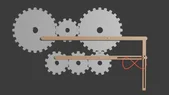
For a project I'm starting now, I'd need to convert a circular motion generated from an electric motor into a loop shaped as an ∞ , through any combination of gears, leverages or mechanical intermediation . So that at a certain level of the system, one fix point attached onto any of those gears would draw a ∞ shaped loop. Then understanding which elements (size/shape) define the sizes of ∞ movement.
Finally that point should possibly be always on top of any other mechanical element so that during the overall system revolutions it doesn't get overlapped by others.
Maybe there's an easy solution but I can't figure it out on the spot.
Finally that point should possibly be always on top of any other mechanical element so that during the overall system revolutions it doesn't get overlapped by others.
Maybe there's an easy solution but I can't figure it out on the spot.