parm09
- 4
- 0
Can someone please help me out with this problem? I am not sure if what I am doing
question:
The figure below shows the internal wiring of a "three-scale" voltmeter whose binding posts are marked , 3.00 V, 15.0 V, and 150 V. When the meter is connected to the circuit being measured, one connection is made to the post marked + and the other to the post marked with the desired voltage range. The resistance of the moving coil is Rg, and a current of I in the coil causes it to deflect full scale.
Picutre:
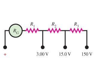
we know v=i/r and Vcoil=IgRcoil
dont know where to begin
question:
The figure below shows the internal wiring of a "three-scale" voltmeter whose binding posts are marked , 3.00 V, 15.0 V, and 150 V. When the meter is connected to the circuit being measured, one connection is made to the post marked + and the other to the post marked with the desired voltage range. The resistance of the moving coil is Rg, and a current of I in the coil causes it to deflect full scale.
Picutre:
we know v=i/r and Vcoil=IgRcoil
dont know where to begin
Attachments
