Calculating torsional stresses in welds that don't fit standard cases

Join the discussion
Registration is free. Ask a follow-up in this thread, or start your own.
1 reply · 3K views
Kiblur
Messages
7
Reaction score
2
1716347393794.png


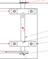
I was required to calculate the torsional stresses on these welds (in green) with the point of rotation G. However this doesn't fit any case in Shigley's so I'm at a loss as to how I should have calculated this. As advised by the teacher, I ended up replacing the keys being welded with full length keys so it would fit a case that I could use. However, that's just bad design. This isn't the first time I've had trouble calculating torsional stress because of an oddly shaped element. Below is another case I encountered. I would like to learn to calculate odd cases like this. Does anyone know of any resources that can help? Thank you very much.

1716347900938.png
 
Attachments
  • 1716347328126.png
    1716347328126.png
    7.7 KB · Views: 114
Physics news on Phys.org
Kiblur said:
So you have the circumference indicated by the arrow in green welded and then torsion is applied there. I think you can approximate the stress at the welds with the torsion divided by the area of the weld. Another issue is how that torsion will travel through your part. I'd say the most critical section is the space in the middle where only two arms are supporting the load. The section there isn't a cylinder but comes from one. I feel like the results from the formula 3-36 from Shigley's should be somewhat precise.
$$\tau = \frac{T\rho}{J}$$
You'd need to calculate the polar moment of that section but that's doable without too much trouble because of the radial nature of the cross-section.
1716653033487.png

Of course, if you have the chance, correlate your hand-made results with FEA. Or even better, with experimental results.