Compound planetary gear problem

AI Thread Summary
The discussion revolves around a problem involving compound planetary gears, where the user seeks assistance in calculating the final speed and torque of an engine connected to a ring gear with specific teeth configurations. The user has provided details about weights, gear dimensions, and desired outcomes but is unsure how to apply the relevant formulas for these calculations. There is confusion about whether to calculate the number of teeth randomly or follow a specific formula, as well as how to approach the torque calculations for the mechanism. The user aims to achieve a rotational speed of 1600 RPM to power an LED, relying on gravity to assist in the mechanism's operation. Overall, the user is looking for guidance on starting the calculations and understanding the necessary formulas for this compound gear system.
Pawllentiew
Messages
11
Reaction score
1
Hi, I need a little help with this problem with compound planetary gears. I don't know how to apply the formulas for this specific type of placement.

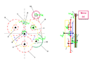
I need to know the final speed of the engine knowing the number of teeth z1 = -104 ring gear which is internal, z2,3,4 = 22 for small planets, z5,6,7 = 65 for large planets, z8 = 17 for the small sun, z9 = 95 for the big sun and z10 = 13 for spool gear.

A weight of 12kg will be attached to the ring gear on one side and 2kg of counterweight on the other from a height of 2 m. I want to calculate the speed and torque that the engine will have if I want the weight to fall within 20 minutes from the 2m.

And i also need the ratio that the system have. The modulus of the wheels is 0.8 and the pressure angle is 20. I also know that the spool from the z10 have diameter equal to 30 mm and the one from the motor have 15 mm. These are the data I know and don't really know how to apply it. Can someone help me?
 

Attachments

  • Untitled-1.png
    Untitled-1.png
    21.4 KB · Views: 230
Last edited by a moderator:
Engineering news on Phys.org
Pawllentiew said:
Hi, I need a little help with this problem with compound planetary gears.
It looks like this is a continuation of another thread that you already have going in the schoolwork forums. Please continue posting your work in that thread. This new thread is closed.

Feel free to send me a message if for some reason this is a new project not related to schoolwork. (Click on my avatar and "Start a conversation").

From your other thread:

Pawllentiew said:
Hi, I've been pretty busy for the last few weeks but I've managed to make a scheme. I'm not good at this. It's the first time I've received something like this to do. so it's probably wrong. That's why I need some clarification if anyone offers to give it to me.

I don't know how to start the calculations for this mechanism. Should I calculate the number of teeth? How do I do this if I don't have the mechanism and I'm just trying to create it from scratch? Do I randomly put the number of teeth or do I have to follow a formula? What is that formula for this mechanism?

After finding out the number of teeth how should I create the formulas to find out the torque for my mechanism? do I break down the mechanism in the part that contains sun gear, planet gear, ring gear and the part that contains the sprocket for the belt and the belt? Do I calculate them when they are decomposed or do they have to be calculated together to find out the torsion or the rest of the parameters? And what would be the formula that emerges in any case?

I really don't know how I should start and where to start. a few formulas would help me answer these questions. This mechanism aims to increase the rotation enough to rotate the dc motor at a speed high enough (1600 rpm) to turn on an LED. Basically, a rope is glued to a ring gear to which a weight and a counterweight are attached. Gravity helping the mechanism to rotate, ring gear is the input. From this ring gear the rest of the components should increase their speed until the engine starts that led of about 15 lumens. I know that for this LED it takes 1600rpm to start with the engine.

How do I find the required initial speed with which the ring gear must rotate when the weight is falling. I'm very stuck because I don't know what to start with and what are the formulas needed for this kind of mechanism with just this information I have. I only own what the mechanism looks like as a drawing. but without number of teeth or other dimensions
 
Thread 'What type of toilet do I have?'
I was enrolled in an online plumbing course at Stratford University. My plumbing textbook lists four types of residential toilets: 1# upflush toilets 2# pressure assisted toilets 3# gravity-fed, rim jet toilets and 4# gravity-fed, siphon-jet toilets. I know my toilet is not an upflush toilet because my toilet is not below the sewage line, and my toilet does not have a grinder and a pump next to it to propel waste upwards. I am about 99% sure that my toilet is not a pressure assisted...
After over 25 years of engineering, designing and analyzing bolted joints, I just learned this little fact. According to ASME B1.2, Gages and Gaging for Unified Inch Screw Threads: "The no-go gage should not pass over more than three complete turns when inserted into the internal thread of the product. " 3 turns seems like way to much. I have some really critical nuts that are of standard geometry (5/8"-11 UNC 3B) and have about 4.5 threads when you account for the chamfers on either...
Thread 'Physics of Stretch: What pressure does a band apply on a cylinder?'
Scenario 1 (figure 1) A continuous loop of elastic material is stretched around two metal bars. The top bar is attached to a load cell that reads force. The lower bar can be moved downwards to stretch the elastic material. The lower bar is moved downwards until the two bars are 1190mm apart, stretching the elastic material. The bars are 5mm thick, so the total internal loop length is 1200mm (1190mm + 5mm + 5mm). At this level of stretch, the load cell reads 45N tensile force. Key numbers...
Back
Top