Fluid dynamics with T-junction vs separate riser in tank pipe system

  • Thread starter Thread starter questionpanda
  • Start date Start date
Join the discussion
Ask a follow-up here, or get your own question answered by working scientists, mathematicians and engineers — people, not an autocomplete.
Real named experts · corrections over time · the nuance an AI answer skips
6 replies · 413 views
questionpanda
Messages
3
Reaction score
1
TL;DR
Question about fluid dynamics in a pipe system to help minimise water overflowing at its source in a basic rainwater system setup using a supplementary tank inlet.
Hi there!

First time poster. Hopefully posting to the correct forum :smile:

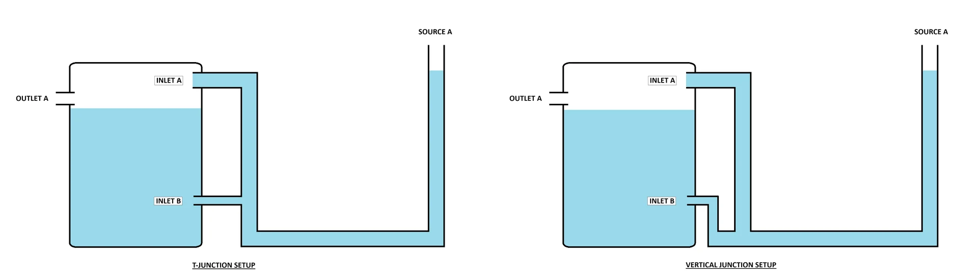
The attached image has two different pipe setups.
fluid_dynamics_tjunc_vs_sup.webp


Both setups have a tank with an upper inlet (A) and a lower inlet (B). Inlet B is half the diameter of inlet A.

The setup on the left hand side has inlet B connected as a T-junction to the vertical pipe that feeds water to inlet A.

The setup on the right hand side has inlet B connected to a small vertical riser connected to the main branch of the pipe system.

Water fills the pipe from source A and initially enters the tank via the smaller inlet B.

As water continues to fill the pipe system, the level in the tank and pipe rises.

At some point, water in the pipe system will start entering the tank from the upper inlet A as the water level in the pipe system rises.

Which setup would less likely cause the source point A to overflow if the incoming supply of water is coming in quicker than what the pipe system and tank inlets A and B can cope with?

I have a very limited understanding of fluid dynamics and my initial research using (freely available) AI chatbots has helped me to understand a little about "head pressures" and "communicating vessels". However, the AI chatbots often come up with contradictory answers to my question as to which system is better suited to prevent overflows at the source.

The background to this question is in regards to a rainwater harvesting system that uses charged downpipes (otherwise known as a 'wet system) to fill a water tank. The current system tends to overflow at the source (downpipe) during heavy rain. A rainwater harvesting forum suggested adding a supplementary inlet (B) to the water tank to provide some relief to the main inlet (A).

I would appreciate if some one can better explain in (basic terms) the "fluid dynamics" that are occurring in the different setups.
 
Physics news on Phys.org
questionpanda said:
TL;DR: Question about fluid dynamics in a pipe system to help minimise water overflowing at its source in a basic rainwater system setup using a supplementary tank inlet.

A rainwater harvesting forum suggested adding a supplementary inlet (B) to the water tank to provide some relief to the main inlet (A).
The inlet B with the riser will flow less than the inlet B with the T because of less restriction from elbows. If the supplementary inlet B is smaller than the inlet A, then it will make very little difference to the total flow. Some things you can do to improve flow:

1) Larger pipe.
2) Raise the inlet height.
2) Change elbows to long sweep elbows.

A diagram showing pipe lengths and diameters would help us to give better answers.
 
Reply
  • Like
Likes   Reactions: Lnewqban
Welcome!
Assuming everything else being equal, the T-junction setup seems to present less resistance to the path of water to the point of discharge B into the tank (1 elbow + 1 tee).
That is for the described dynamic situation (flowing water).
 
At jrmichler request, I have updated the diagram to include some dimensions.
fluid_dynamics_tjunc_vs_sup_dimen.webp

The original post only showed a single Source (A), however the actual system has two sources/downpipes. Not sure if this complicates things :confused:

From the research using the AI chatbots, I believe there are multiple fluid dynamic principles that are taking effect in these setups.

With the left hand side setup, there is "head" pressure in the vertical pipe that feeds inlet A and B, in that additional height of water in the vertical pipe will assist the flow into inlet B.

In comparison, the right hand side has separate vertical pipes that feeds inlet A and B. From my understanding, the head pressure in the vertical column that feeds inlet A has not effect on the head pressure at inlet B. However, the AI chatbots indicate that "communicating vessels" is taking effect in this right hand side setup.

I assuming that while the level of the water in the tank is low, both setups would work very similarly.

However, how would these two systems behave when the tank level is near to its full capacity? With the left hand side setup, I'm assuming that the head pressure in the vertical pipe will be able to push water into the tank via inlet B as well as inlet A? With the right hand setup, I'm assuming there would only be flow at inlet B as long as the water level from source A and B is higher than the water level in the tank, otherwise there would be no flow as the system is at equilibrium? Therefore, which of these two setups would be better are preventing or minimizing the sources A and B potentially overflowing in heavy rain events?

Will having this lower inlet B on the water tank actually cause water to flow back towards the sources A and B if there are any surges of water in the water that causes water in the tank to bob up and down? That is, would the bobbing of water in the water tank try to "equalize" it's level across the whole system (thus potentially causing water to overflow at the source points)?

I'm wondering whether the rainwater harvesting forum that suggested adding a supplementary inlet (B) to the water tank to provide some relief to the main inlet (A) is actually a good idea or not? :confused:
 
Reply
  • Like
Likes   Reactions: Lnewqban
We do not allow AI chatbots on the technical forums because their output cannot be trusted, and is frequently wrong. In your case, the AI is misleading you.

Water flows downhill. If the water level in the Source A pipe is different from the water level in the Source B pipe, it will flow from the higher level toward the lower level. If the water level at the sources is higher than the water level in the pipe at the tank inlet, it will flow toward the tank.

The water flow rate depends on the difference in heights between the sources and the tank, and the resistance to flow of the pipe system. The larger the height difference, the larger the flow. The less the pipe resistance, the larger the flow. The height of the inlet restricts flow whenever the inlet is above the tank water level because you are pushing water uphill and letting it fall downhill. A straight length of pipe has a resistance to flow. Each elbow adds a lot of resistance to flow.

You could make one change and get a large increase in flow. Extend the horizontal 11.2 m pipe straight into the side of the tank. You eliminate a length of pipe, eliminate two elbows, and increase the height difference. Forget the supplementary input B. The flow through 50 mm pipe is a small fraction of the flow through 100 mm pipe, so would make only a small difference in total flow.
 
You could make one change and get a large increase in flow. Extend the horizontal 11.2 m pipe straight into the side of the tank. You eliminate a length of pipe, eliminate two elbows, and increase the height difference. Forget the supplementary input B
I assume the length of pipe you suggest eliminating is the vertical riser to the tank inlet?

Extending the horizontal 100mm (4") pipe into the side of the tank may be problematic. Due to the curvature of the water tank side wall, it will be difficult to fit a 100mm (4") bulkhead fitting to the tank without requiring the making of a custom gasket/adapter to provide a proper watertight seal on the curved tank wall.

I have been able to make a prototype gasket using a RTV based silicone in a 3D printed mold to suit a 50mm (2") bulkhead, which looks like it should work. Creating a 100mm (4") version would require a deeper mold requiring the silicone to be applied to several layers to aid curing.

custom gasket.webp