Help with the equations for this "sideways differential" please

  • Thread starter Thread starter schofieldius
  • Start date Start date
  • Tags Tags
    Differential
Join the discussion
Registration is free. Ask a follow-up in this thread, or start your own.
24 replies · 3K views
schofieldius
Messages
14
Reaction score
0
TL;DR
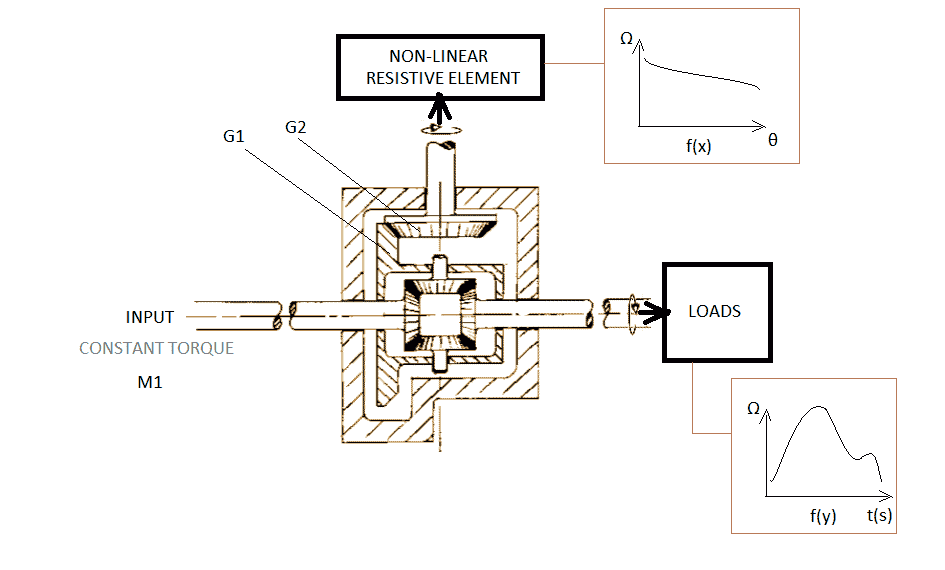
I would like some help working out equations for this strange set-up of a differential. I'm trying to reverse engineer something I invented a different way from how it should be described. I am trying to see how a nonlinear resistance acting on the differential casing adds or subtracts torque from the input torque going into the loads. F(x) describes resistance vs angular displacement of the differentials casing and F(y) describes some loads changing over time.
looking for some assistance working out torque equations for this set-up please.
question.png
 
Last edited by a moderator:
Physics news on Phys.org
schofieldius said:
Summary:: I would like some help working out equations for this strange set-up of a differential. I'm trying to reverse engineer something I invented a different way from how it should be described.

looking for some assistance working out torque equations for this set-up please.
Welcome to the PF. :smile:

Please define each of the variables that you have listed in your drawing, and please describe in words what you are trying to achieve with this differential mechanism. Thank you.
 
berkeman said:
Welcome to the PF. :smile:

Please define each of the variables that you have listed in your drawing, and please describe in words what you are trying to achieve with this differential mechanism. Thank you.
Thank you for your reply. G1& G2 describe the differentials gearing between input and the resistive element. I want to know how to model the torque response of such a system. I have nominated omega to represent mechanical resistance (both in the resistive element and load).
 
schofieldius said:
Thank you for your reply. G1& G2 describe the differentials gearing between input and the resistive element. I want to know how to model the torque response of such a system. I have nominated omega to represent mechanical resistance (both in the resistive element and load).
What are f(y) and t(s)?

What are f(x) and ##\theta## ?
 
berkeman said:
What are f(y) and t(s)?

What are f(x) and ##\theta## ?
F(x) is a function of resistance vs angular displacement of the differentials casing.
F(y) describes some load resistances against time in seconds, t(s).
I may be using strange terminology.
 
schofieldius said:
F(x) is a function of resistance vs angular displacement of the differentials casing.
F(y) describes some load resistances against time in seconds, t(s).
I may be using strange terminology.
Yes, so far you are, but we'll try to adapt. Please re-state your question while defining all of your variables and assumptions. Time in seconds is t(s)? What is "s", units? And your notation for units is different from F(x) and F(y)? Can you also define your coordinate system and origins please?
 
berkeman said:
Yes, so far you are, but we'll try to adapt. Please re-state your question while defining all of your variables and assumptions. Time in seconds is t(s)? What is "s", units? And your notation for units is different from F(x) and F(y)? Can you also define your coordinate system and origins please?
T(s), time in seconds. I've rewrote the question.
 
schofieldius said:
T(s), time in seconds. I've rewrote the question.
Sorry, it still makes no sense. This is what you re-wrote to be more clear?

F(x) describes resistance vs angular displacement of the differentials casing and F(y) describes some loads changing over time.

Angular displacement should be ##\theta##, and force as a function of time would be F(t), not F(y). Angular "resistance" would be a torque ##\tau## and not a force F.

We would like to help you, but so far your question is quite confused and confusing. Can you please take some time to reformulate your drawing and problem statement in terms of standard terminology and repost the whole thing as a new reply below? Thank you.
 
berkeman said:
Sorry, it still makes no sense. This is what you re-wrote to be more clear?
Angular displacement should be ##\theta##, and force as a function of time would be F(t), not F(y). Angular "resistance" would be a torque ##\tau## and not a force F.

We would like to help you, but so far your question is quite confused and confusing. Can you please take some time to reformulate your drawing and problem statement in terms of standard terminology and repost the whole thing as a new reply below? Thank you.

I don't know standard terminology, I'm struggling with this.
 
1595807150018.png

is this a better image to rewrite my question from?
 
I'm an electronic engineer, but not a very good one. But I do have something here- you should see the stinking maths involved in the rest of the system! I had to go to too many people before realising the answer sat in Horology.
 
schofieldius said:
View attachment 266906
is this a better image to rewrite my question from?
It looks much better! So the angular "non-linear" resistive load is a torque ##\tau## = ##f(\theta)## ?

But what is this?

1595807559281.png
 
berkeman said:
It looks much better! So the angular resistive load is a torque ##\tau## = ##f(\theta)## ?

But what is this?

View attachment 266907
road resistances
 
schofieldius said:
I'm an electronic engineer, but not a very good one. But I do have something here- you should see the stinking maths involved in the rest of the system! I had to go to too many people before realising the answer sat in Horology.
Horology? The study of time? Sorry, that is not helpful.

I'm an EE as well, but I understand ME concepts well enough to write torque balance equations for a transmission. And even in EE, we need to make our equations and graphs make sense, no?
schofieldius said:
road resistances
The labels on that graph make no sense. Can you please define each term on that graph, and give an example? And what leads to the shape of that curve? Some loss of traction?
 
a clockwork mainspring, but I don't want to say that or the illustrated graph to give it away. I have designed a very simple CVT using a pullback motor as a sort of KERS system. I am trying to explore the torque response of a "sideways" differential with it's casing geared to a mainspring component.
 
schofieldius said:
a clockwork mainspring, but I don't want to say that or the illustrated graph to give it away. I have designed a very simple CVT using a pullback motor as a sort of KERS system. I am trying to explore the torque response of a "sideways" differential with it's casing geared to a mainspring component.
 

Attachments

  • Screenshot_20200726_174729.jpg
    Screenshot_20200726_174729.jpg
    49.6 KB · Views: 332
The real curve
 

Attachments

  • Screenshot_20200726_174112.jpg
    Screenshot_20200726_174112.jpg
    32.7 KB · Views: 299
schofieldius said:
The real curve
 
I won't post my prototype videos, but it does work and I'm trying to understand why so I can simulate and design it further
 
schofieldius said:
I won't post my prototype videos, but it does work and I'm trying to understand why so I can simulate and design it further
I can SEE why it works, I need to know how the math works I can SEE the curves interaction in my mind, but I can't do it on paper or software yet
 
schofieldius said:
I can SEE why it works, I need to know how the math works I can SEE the curves interaction in my mind, but I can't do it on paper or software yet
Input torque should be transferred to the load (in reverse rotation): same torque and rpm’s values.
As load resistance increases and the rpm’s of the output shaft decrease respect to the rpm’s of the input shaft, some work will begin to be transferred to that non-linear resistive element.
Note that the torque transferred to that element will be reduced because the rpm’s will be increased, due to the ##G_1/G_2## gear ratio.

Sorry, I am unable to help you with the equations, but I believe that the input and output torques will exactly reflect the non-linear resistance of the element.
Perhaps, this could help you:
https://x-engineer.org/automotive-e...hicle-dynamics/calculate-wheel-torque-engine/

:cool:
 
  • Like
Likes   Reactions: schofieldius
schofieldius said:
I can SEE why it works, I need to know how the math works I can SEE the curves interaction in my mind, but I can't do it on paper or software yet
If you can see how it works, then you can see that a constant input torque means that the other two shafts will also have a constant torque. The output shaft will have the same torque as the input shaft, but in the opposite direction. The middle shaft will have a constant torque, the magnitude of which will be a function of the gear ratio. In order to solve for the speeds, you will need an inertia in the system. Otherwise, the speed will instantly go to either zero or infinity.

You mention a "nonlinear resistive element" and a "clockspring". These are two different things. A resistive element could be a friction brake that dissipates energy, but does not store it. A clockspring can store energy, but is inherently linear.

A spring, whether a clockspring, leaf spring, or coil spring, can only store a limited amount of energy. I suggest that you calculate the amount of energy stored in a spring. Then compare to the amount of energy to, for example, accelerate a motor vehicle to a given speed. You will quickly find why springs are not used in KERS systems. I can highly recommend the SMI Handbook of Spring Design as a resource for learning about springs: https://smihq.org/store/ViewProduct.aspx?id=8525988. Search term energy storage spring will also find some good information.
 
  • Like
Likes   Reactions: BvU, berkeman and Lnewqban
Using the notation you used in post #17 to identify the different axles (A, B, C), the constraint equations for torque ##T## are:
$$T_A = T_C = \frac{N}{2}T_B$$
Where ##N = \frac{R_{G1}}{R_{G2}}## (the gear ratio).

The constraint equation for the angular velocities ##\omega## (i.e. rpm) is:
$$\omega_B = \frac{N}{2}(\omega_A + \omega_C)$$
(if one ##\omega## is negative, it means it turns in the other direction.)

And, of course, the power ##P## to each axle is defined the usual way:
$$P_A = T_A \omega_A$$
$$P_B = T_B \omega_B$$
$$P_C = T_C \omega_C$$
 
  • Like
Likes   Reactions: Lnewqban
jrmichler said:
If you can see how it works, then you can see that a constant input torque means that the other two shafts will also have a constant torque. The output shaft will have the same torque as the input shaft, but in the opposite direction. The middle shaft will have a constant torque, the magnitude of which will be a function of the gear ratio.
No, the output shaft will only have an opposite torque to the input shaft if there is no torque on the middle shaft. If there is torque on the middle shaft, it will bias the torque on both the input and output shaft in the same direction. This is also the general operating principle of a car differential, though in cars, the input is actually the middle shaft and then both the "input" and "output" in this diagram are outputs, one connected to each wheel.
 
  • Like
Likes   Reactions: jrmichler