Rotating mirror system for shifting a beam?

Join the discussion
Registration is free. Start your own thread to ask a follow-up.
14 replies · 3K views · last reply
wosoka
Messages
44
Reaction score
2
(sorry if posting in the wrong place)

I am looking for some mirror setup where rotation one or more elements in the mirror setup will allow to shift the beam along its axis.

Two mirrors in a galvanometer scanner type setup work well for controlling the angle of the beam.

Rotating risley prisms can be used to only offset the beam without changing its angle but the possible positions are limited.

Dove prisms are great for rotating the beam along itself or rotate in a circular fashion if prism center is shifted.

But as for offsetting (shifting) a beam along its axis from a (-1,-1) position to (1,1) without changing the angle of the beam, I can't find any setup which involves a rotating mirror rather than shifting mirror. But I feel there may be something missing from my limited optics knowledge.
 
Physics news on Phys.org
Hi and welcome to PF.
It's not obvious to me what the context of this is but you can use a parallel sided block to shift a beam laterally. Would that be worth considering?
 
This is one of those times where pictures are needed.

Here is what I think you are saying:
"I need a way to flip an image vertially and horizontally, whilst maintaining the angle of the light"

If this is the case, then I suggest Schmidt–Pechan prisms or Abbe–Koenig prisms
Schmidt-Pechan_prism.svg

Abbe-K%C3%B6nig_prism.svg
 
No not flip, but shift, or offset. Sorry for poor explanation.

Diagram of a box-shaped mirror assembly with a red beam entering from below at the centre and exiting upward; red X and green Y axes with labels -1 and 1 show the beam offset range, with handwritten annotations describing a mirror setup with rotating mirrors.
 
Attachments
  • Diagram of a box-shaped mirror assembly with a red beam entering from below at the centre and exiting upward; red X and green Y axes with labels -1 and 1 show the beam offset range, with handwritten annotations describing a mirror setup with rotating mirrors.
    3qkvRpS.jpg
    25.7 KB · Views: 1,164
  • Like
Likes   Reactions: Shadow89
wosoka said:
No not flip, but shift, or offset. Sorry for poor explanation.

View attachment 223015

Thank you for the excellent drawing. Now I know what you are asking.
I will assume now, that what you call a "beam" is in fact one beam of light traveling parallell in a very small diameter cross section. I.e. a laser beam. Correct?

If this is the case, I would revert back to mirrors, as you yourself have suggested. Can you put a series of mirrors on a 45 degree angle and manipulate them using servo motors? This is what they do on Laser engraving machines.

Desktop laser engraver with a blue-violet laser head on an aluminium gantry over a flat white bed, a small disc in the centre, beside a laptop showing control software.

Close-up of a laser engraving machine's moving head, with a cylindrical focusing lens holder, a yellow and black laser warning label, and a cable running down from the carriage above a metal ruled measuring plate.
 
Attachments
  • Desktop laser engraver with a blue-violet laser head on an aluminium gantry over a flat white bed, a small disc in the centre, beside a laptop showing control software.
    maxresdefault.jpg
    32.6 KB · Views: 664
  • Close-up of a laser engraving machine's moving head, with a cylindrical focusing lens holder, a yellow and black laser warning label, and a cable running down from the carriage above a metal ruled measuring plate.
    Laser_Engraver.jpg
    37.1 KB · Views: 740
I am looking for a method which will involve rotating (tilting) mirrors instead of offsetting (moving). The latter is just heavier and slower. For CNC it works great because speed is limited by cutting time anyway, allows to have very large offsetting and doesn't cause power loss. But not suitable for my use case as those are not an issue or requirements and speed is an issue. I just need to offset 10mm in both axis.
 
wosoka said:
6x6x8 cm probably

If it weren't for your space limitations, I would suggest using a thick slab of glass of the appropriate refractive index (as high as possible).
You could use two in sequence, each rotating about its own axes. i.e. rotate slab 1 along x axis, rotate slab 2 along y axis, send beam along z axis.

Two ray diagrams of a light beam passing through a thick glass slab, showing the beam bending at each air-glass interface and emerging parallel to its original path, displaced sideways by a lateral shift.


You can cut the corners on the glass slabs to save some space.
Edit: Also you might suffer some abberation due to differential refraction of different frequencies of light, unless you are using a laser of one speciffic frequency. Just a disclaimer.
 
Attachments
  • Two ray diagrams of a light beam passing through a thick glass slab, showing the beam bending at each air-glass interface and emerging parallel to its original path, displaced sideways by a lateral shift.
    a_23_4.png
    4 KB · Views: 673
Last edited:
What will the calculation be for determining how much offset I will get given a slab refractive index, slab thickness, slab angle relative to beam variables?
 
wosoka said:
What will the calculation be for determining how much offset I will get given a slab refractive index, slab thickness, slab angle relative to beam variables?


Also, what is this for again?
 
  • Like
Likes   Reactions: wosoka
Also, what is this for again?
Oh where do I even begin.
I can say this is for pico video projection beam and I've tried laser scanners and while they are cheap (the "slow" ones) and easy to control, the distortion of the beam caused by angles of the scanner mirrors is hard to correct by undistorting the pixels in software and results in loss of resolution. Something which would be perfect would be to be able to offset the tiny projection beam without affecting its angle. I had some luck with a gantry system and stepper motors as well like in the CNC you linked to but it was just not fast enough, although close.

I sure hope some version of PMMA can be used as glass will be pretty heavy.
 
wosoka said:
Oh where do I even begin.
I can say this is for pico video projection beam and I've tried laser scanners and while they are cheap (the "slow" ones) and easy to control, the distortion of the beam caused by angles of the scanner mirrors is hard to correct by undistorting the pixels in software and results in loss of resolution. Something which would be perfect would be to be able to offset the tiny projection beam without affecting its angle. I had some luck with a gantry system and stepper motors as well like in the CNC you linked to but it was just not fast enough, although close.

Ok, that sounds interesting. Make sure you don't shine lasers in anyones eyes though. Thats always bad. Good luck with your project and i hope you learn something! :)
 
Thanks.
The light source is LED not laser although I've built some 10W laser projectors before and am aware of eye safety.
 
  • Like
Likes   Reactions: Shadow89
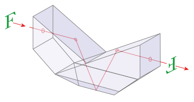
I think the same effect can also be achieved with two bounce mirrors attached together and rotating around a center point, yes? With an acrylic first surface mirrors would weigh a lot less.