Static Mechanics: Aircraft Nosewheel Linkage Torque

  • Thread starter Thread starter jojosg
  • Start date Start date
Join the discussion
Registration is free. Ask a follow-up in this thread, or start your own.
4 replies · 2K views
jojosg
Messages
37
Reaction score
5
Homework Statement
Hi I'm stuck at how to draw the free body diagram for thise nose wheel question
Relevant Equations
Moment equal 0
see attached

mmexport1760866157266.webp


IMG_20251019_172253.webp
 
Last edited by a moderator:
Physics news on Phys.org
A free body diagram shows the forces on a single rigid body. Here you have a linkage, so you need an FBD for each moving part. This will involve defining unknowns for forces and torques between connected bodies, each such force being represented in the FBDs for both bodies.
What are the moving rigid bodies in this problem? Pick one and list the forces on it. Then post your attempt at its FBD.
 
I think it is safe to assume that links BC and CD are massless because no masses are given for them. Assume that the torque at M gives rise to a force ##F_D## at D that is just right to prevent the combined (arm + wheel) assembly AO from rotating either clockwise or counterclockwise.
 
Consider the external force and moment acting on the whole mechanism first.
One is the represented M, which is necessary to raise the combined mass of 50 kg, which can be represented as a vertical force applied at point G.

Note that the value of that vertical force will be constant, while the value of the necessary moment M will change as the wheel is being raised, reason for which the problem asks for the value of moment M at that specific position of the mechanism's stroke.

Please, see this example:
https://www.school-mechademic.com/blog/static-force-analysis-on-a-4-bar-link-mechanism

:cool:
 
Last edited:
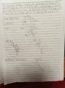
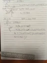
ok I think I got it thanks everyone
 

Attachments

  • IMG_20251020_190101.webp
    IMG_20251020_190101.webp
    30.5 KB · Views: 47
  • IMG_20251020_190106.webp
    IMG_20251020_190106.webp
    30.8 KB · Views: 49