Calculating moments about a point and counting constraint forces

7 replies · 2K views · last reply
Yossi33
Messages
22
Reaction score
3
Homework Statement
classify structures as completely ,partially or improperly constrained
Relevant Equations
first and third law of newton
hello, i struggle with this kind of questions and i don't understand the way of thinking and how to solve this.
Hand-drawn truss diagram labeled Structure (c): a triangular-topped truss with loads P, P and F1, F2 at joints, supports Ax and Ay at the left, spans marked a, a, a, with printed text beneath.


in the first picture i don't understand why Moments about point Aare a*F1 because there is the 2 P forces that do moments.?
in the second problem i can't understand why there are 3 forces at B in the left side picture and 2 at the right ?
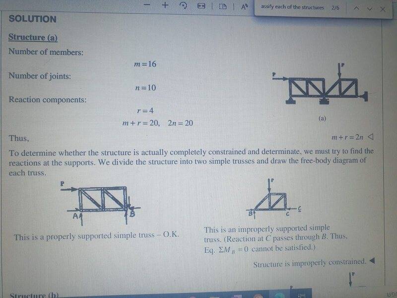
Printed solution page for a truss structure (a): member count m = 16, joint count n = 10, reaction components r = 4, with m + r = 2n, and a free-body split into two simple trusses with supports A and B and a lower-right truss with joints B and C.

and the third picture how can i know if this structure is properly constrained or not?
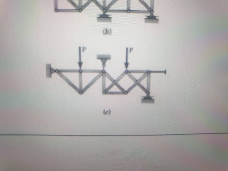
Partial truss diagram labeled (b) with a pin support and roller support on the bottom chord; below it, truss (c) with a left wall fixed support, two downward loads labeled P, a central pin support, and a right roller support on the bottom.

thanks a lot
 
Attachments
  • Truss diagram labeled (c) with a wall support at the left end and two downward loads P applied at upper joints, a pin support at the middle top, and a roller support at the lower right.
    WhatsApp Image 2022-04-24 at 12.35.24 (2).jpeg
    19.9 KB · Views: 157
For case 1: Any force, which extended line does not pass by pivot A will cause a moment about that point.
Based on that, force F1 will induce a moment, but F2 will not.
 
For case 2:
Left half of the armature: The vertical arrow pointing down and the horizontal arrow pointing left on B are just the reflection of the forces acting on pivot B shown on the right half of the armature.

Therefore, you should consider those forces as external loads, rather than reaction forces at sliding support B (which is unable to oppose any horizontal load).

Sliding support B is only transferring the horizontal force (represented by equal magnitude and opposite directions) between horizontal force P and horizontal support C.

B is inducing a unique vertical reaction, which is represented in both halves.
 
For case 3: Learning how to determine that is the whole point of that book chapter.
Without doing the calculations, I can see that the left side is properly constrained, but the right side is not, as some of its members have freedom to rotate under the load of vertical force P.
It needs, either a vertical member under P or a horizontal restriction where the slider is now located at.

Truss diagram labeled (c) with loads P applied downward at two joints, a pinned support at the left wall, and a roller support at the right end; red lines trace members and an arrow indicates a horizontal direction.
 
Last edited:
Yossi33 said:
in the first picture i don't understand why Moments about point Aare a*F1 because there is the 2 P forces that do moments.?
The book's explanation looks inaccurate. The total moment about A is ##aF_1 + aP + 2aP##. This is clockwise, with no counterclockwise moment to balance it, i.e. it is non-zero. But the conclusion that there is no equilibrium is still correct.
 
But if f1 is compression instead of tension it will be clockwise and counter the p forces moment? why to assume it’s only directions is tension ?
 
Yossi33 said:
But if f1 is compression instead of tension it will be clockwise and counter the p forces moment? why to assume it’s only directionsI is tension ?
Are you replying to my Post #5? If so, note that ##F_1## is an external force and its direction is given in the diagram.

It acts right and its line of action is above point A. So it must produce a clockwise moment about A.
 
Steve4Physics said:
If so, note that ##F_1## is an external force and its direction is given in the diagram.
@Yossi33, if ##F_1## is not an external force (with given direction), I can't understand the question and accompanying solution.