Circuit Analysis Theorem For the Number of Independent Equations

Click For Summary
SUMMARY

The discussion centers on the application of the circuit analysis theorem, which states that for a circuit with m currents and n nodes, there are n - 1 independent equations from Kirchhoff's Current Law (KCL) and m - n - 1 from Kirchhoff's Voltage Law (KVL). In the example provided, with 4 nodes and 6 currents, the expected equations are 3 from KCL and 1 from KVL, totaling 4 equations. However, the author notes a discrepancy, as they derive 6 equations, indicating a misunderstanding of the concept of independent equations. The discussion further explores the relationship between circuit theory and polyhedral geometry, emphasizing the topological aspects of circuit analysis.

PREREQUISITES
  • Understanding of Kirchhoff's Current Law (KCL)
  • Understanding of Kirchhoff's Voltage Law (KVL)
  • Familiarity with circuit topology and polyhedral geometry
  • Basic knowledge of independent equations in linear algebra
NEXT STEPS
  • Study the implications of Euler's Law of Polyhedra in circuit analysis
  • Learn about the concept of nullspace and degrees of freedom in linear systems
  • Explore advanced circuit analysis techniques using mesh and nodal analysis
  • Investigate the relationship between circuit theory and graph theory
USEFUL FOR

Electrical engineers, circuit designers, and students of electrical engineering seeking to deepen their understanding of circuit analysis and its mathematical foundations.

rtareen
Messages
162
Reaction score
32
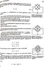
I attached a screenshot of the book (sorry no pdf available for this book). Right above the somewhat central line they give the theorem that if there are m currents and n nodes, then there will be n - 1 independent equations from the current law and m - n - 1 from the voltage law.

I count 4 (branching) nodes and 6 currents. So the number of equations given by the current law is 4 - 1 = 3. Thats fine. But then we should get one more (6- 4 - 1) from the voltage law. But they end up with three more from the voltage law leading to a total of six equations, which they will need because there are six unknown currents.

So what's going on here?
 

Attachments

  • Theorem.jpg
    Theorem.jpg
    76.4 KB · Views: 198
Engineering news on Phys.org
rtareen said:
I count (...) 5 currents (...) because there are six unknown currents.

So what's going on here?

Good question.
 
Borek said:
Good question.
Well I fixed that. It still leads to only one more equation according to this theorem. What else is wrong?
 
What is reference to the book?
 
I think the issue here is "independent equations". You can make lots of equations from KVL & KCL, but you don't need all of them. For example, in the bridge circuit shown, if I told you the values for I1, I2, and I3, couldn't you solve the whole circuit?

But, honestly, I haven't really thought about this much. I never liked the network theory classes I had to take (several decades ago).
 
I've just made a post that ties circuits to polyhedrons. Essentially every node is a vertex, every branch is an edge, and every indivisible loop is a face. There is a current continuity EQ for every node/vertex, and a voltage loop EQ for every loop/face. Because the continuity EQs are all equal to zero, the resultant vector is the zero vector, and thus there is 1 nullspace DOF in that set. And since a polyhedron can topographically be stretched so that 1 face could have the image of all the rest (i.e., a Schlegal diagram), it is a combination of loops, and thus there is 1 nullspace DOF in the set of loop/face EQs - and since there must be an EMF element in some branch to have a non-null system, the resultant vector is not the zero vector, and thus there is no other nullspace DOF. Therefore, the net rank of the combined set is ( # of node/vertices + # of loop/faces - 2 ), which of course as per Euler's Law of Polyhedra is equal to the # of branch/edge currents.

https://www.physicsforums.com/threads/circuit-analysis-via-polyhedron.1050802/
 
Most likely this can only be answered by an "old timer". I am making measurements on an uA709 op amp (metal can). I would like to calculate the frequency rolloff curves (I can measure them). I assume the compensation is via the miller effect. To do the calculations I would need to know the gain of the transistors and the effective resistance seen at the compensation terminals, not including the values I put there. Anyone know those values?

Similar threads

  • · Replies 3 ·
Replies
3
Views
2K
  • · Replies 5 ·
Replies
5
Views
2K
  • · Replies 14 ·
Replies
14
Views
560
  • · Replies 3 ·
Replies
3
Views
2K
  • · Replies 4 ·
Replies
4
Views
2K
Replies
12
Views
2K
Replies
9
Views
2K
Replies
1
Views
2K
Replies
6
Views
4K
  • · Replies 14 ·
Replies
14
Views
8K