shoutie1980
- 2
- 0
Hi All,
So glad to have come across this amazing site and resource.
I am a mature student completing an engineering degree with the Open University and I am after some guidance and help with creating a way to plot forces from a moving mechanical system.
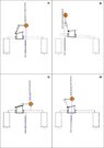
The images on the attached drawing are of a system used in flood protection and i need to find a way of calculating the forces created within the system taking into account gravity, buoyancy and material density and at present I am struggling.
View attachment 5670
I understand that the forces will be angular and as the system moves the angles and therefore resultant forces will change but i am struggling with where to start and am hoping someone can help.
Hopefully this is in someones field,
Thanks in advance,
Anthony
So glad to have come across this amazing site and resource.
I am a mature student completing an engineering degree with the Open University and I am after some guidance and help with creating a way to plot forces from a moving mechanical system.
The images on the attached drawing are of a system used in flood protection and i need to find a way of calculating the forces created within the system taking into account gravity, buoyancy and material density and at present I am struggling.
View attachment 5670
I understand that the forces will be angular and as the system moves the angles and therefore resultant forces will change but i am struggling with where to start and am hoping someone can help.
Hopefully this is in someones field,
Thanks in advance,
Anthony