Confinement box in the resonator ruins result

  • Thread starter Thread starter yefj
  • Start date Start date
yefj
Messages
61
Reaction score
2
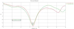
Hello , I have built a resonator as described in the photos and the link in the video below.
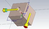
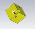
Basickly each coax cable excites a mode in the dielectric saphire cube shown below.
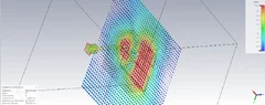
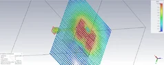
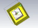
However I need to confine the whole system in a metal box where both exitation connector so outer coax coating connected to the box as shown in the end .
As I do that I get a tottaly different resonance map I get many many spike of resonanse in stead of the original.
I Know that the metal box add lots of capacitance . Is the a way to minimize the effect of the metal box so the resonance will be as if the is no metal box?
Thanks.
2026-02-04 13-49-21.mp4
 

Attachments

  • 1.webp
    1.webp
    19.3 KB · Views: 1
  • 2.webp
    2.webp
    20.1 KB · Views: 1
  • 3.webp
    3.webp
    45.3 KB · Views: 1
  • 4.webp
    4.webp
    43.5 KB · Views: 1
  • 5.webp
    5.webp
    11.2 KB · Views: 1
  • 6.webp
    6.webp
    35 KB · Views: 1
Engineering news on Phys.org
I suspect your problem is more of a wave guide problem than capacitance.
With a 3cm wavelength, your "ground" level will criss-cross the surfaces of the box every which way.
I would use dual-coax, ground the outer layer to the box and use the inner layer and the core for your resonator.

Edit:
I don't know what you signal source is, but I'm suspecting it's just a signal generator. So I just took a look at several 10GHz signal generators. Basically your box needs to be at "chassis ground" and I am not seeing any "chassis ground" connections on the back of most signal generators. So ...
If you haven't already set up an ESD workbench, do that now. Assuming your signal generator is AC powered, it should use have a three-prong electric plug - and that third plug is the ground. Your ESD matt (which will cover your workbench) will also be connected to that ground. And the signal generator itself will likely be sitting on the ESD matt.
So, now your box is basically a chassis. It needs to be grounded to the same point as your matt - and it will be sitting on the matt.
And, of course, you will be wearing a wrist strap tied to the matt ground - which will make it much more difficult for you to destroy the equipment.

I suggest you google "setting up an ESD workstation". I would provide a link, but the instructional pages and videos have a wide range of "personality" best left to your preference.
 
Last edited:
" I am not seeing any "chassis ground" connections on the back of most signal generators"

I connected the box to the outer coating of the coax cables as shown below.
Also I put an absorber that made the situation much better.
However as you could see my mode is only -10dB.
what do you reccomend for improving coupling?
Thanks.

1770223151670.webp

1770223181425.webp
 
yefj said:
" I am not seeing any "chassis ground" connections on the back of most signal generators"

I connected the box to the outer coating of the coax cables as shown below.
Also I put an absorber that made the situation much better.
However as you could see my mode is only -10dB.
what do you reccomend for improving coupling?
You must learn to think about conductive surfaces differently.

At 8 GHz the chassis or external ground connection, between enclosure and generator, will for every half wavelength, cycle once around the Smith Chart, from zero to infinite impedance.

The inside and outside surfaces of the enclosure, are well separated by the skin effect depth in the conductive material. The only place where inside is the same as the outside, is where a poorly connected screen of a coaxial connector, communicates between the two surfaces, appearing like a lossy slot antenna, or a coupling orifice.

An RF absorbent wall will spoil the Q of the resonator, by robbing it of valuable circulating energy. A perfect conductor would make a perfect reflector, so energy that reaches the enclosure wall must be arranged to return to the resonator, with constructive interference.

Look at the conductive enclosure as having mirrors on the inside surface that reflect the image of the resonator. The resonator will see its EM image repeated to infinity in the three dimensions and six directions. Now space the wall mirrors from the transducer to bring the 3D lattice of virtual resonators into phase, and you will see a very significant improvement in the Q of the resonator.

If you design a resonator to have a metallised external surface, then the enclosure will not be needed, and any enclosure dimensions will not be critical. The analysis of the surface conductor, should be as two isolated surfaces, the inside and the outside. At 8 GHz, those surfaces are isolated almost perfectly, by skin effect in the metallisation.