paulimerci
- 287
- 47
- Homework Statement
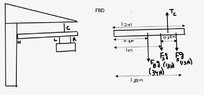
- A sign is suspended from two chains L and R. The chains are attached to a bar B which is supposed by a cable C and held at one end by a hinge H as shown. The mass of the sign is 2.6kg. The two chains have negligible mass, are 0.30m apart and are equidistant from the center of the sign. The bar has a uniform density, has a mass of 3.4kg and is 1.6m long. The cable is attached to the bar 1.2m from the hinge. The left chain L is positioned 1.0m from the hinge.
A) calculate the magnitude of the tension in just the left chain L.
B) determine the tension in the cable C.
The chains that support the sign are attached in such a way that they can slid towards or away from the wall, while still maintaining equal distance from each other and remain vertical.
C) if the sign is moved farther away from the wall, does the magnitude of the force on the hinge H increase, decrease, or stay the same? Justify your answer.
D) sketch a graph of the magnitude of the tension in cable C as the sign is moved further away from the wall. The scale of the y axis is not important, and does not need to be fill in. Only the shape and the location of the intercepts will be considered. The closest the left chain can get to the hinge is 0.30m away, and the maximum distance is 1.3m.
- Relevant Equations
- Torque = F x d
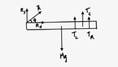
Part -B
$$\sum \tau_{cw} = \sum\tau_{ccw}$$
$$\tau_B=\ torque\ of\ the\ beam $$
$$\tau_S =\ torque\ of\ the\ sign\ board$$
$$\tau_C = \ torque\ of\ the \ cable$$
$$\tau_B+\tau_S = \tau_C$$
$$F_B\cdot d_1 + F_S\cdot d_2 = F_C \cdot d_3$$
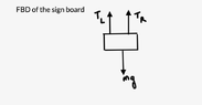
Since the tension in the left and right chains are evenly distributed I took ##F_S## as 13N, 13N and their corresponding distances.
$$ 34\cdot 0.8+13+13\cdot 1.3 = T_C\cdot 1.2$$
$$ T_C = 47.58 ~\rm{N}$$
Now, Part -A of the question,
Where, ##T_L## = Tension in the left chain, ## T_R## = Tension in the right chain
Since the tensions of the left and right chains are evenly distributed,
I take ##T_L## = ##T_R## = T
$$ T_L +T_R = \Weight \of \the \sign \board $$
$$ 2T = 26 ~\rm{N}$$
$$ T =13 ~\rm{N}$$
Part -C
As the sign is moved farther away from the wall, the magnitude of the force on the hinge will increase because torque produced depends on the magnitude of the force and the perpendicular distance between the point about which torque is calculated and the point of application of force. And so as the distance increases magnitude of the force on the hinge will increase. So, mathematically torque is represented as:
$$ \tau = Fr\sin\theta$$
$$\sum \tau_{cw} = \sum\tau_{ccw}$$
$$\tau_B=\ torque\ of\ the\ beam $$
$$\tau_S =\ torque\ of\ the\ sign\ board$$
$$\tau_C = \ torque\ of\ the \ cable$$
$$\tau_B+\tau_S = \tau_C$$
$$F_B\cdot d_1 + F_S\cdot d_2 = F_C \cdot d_3$$
Since the tension in the left and right chains are evenly distributed I took ##F_S## as 13N, 13N and their corresponding distances.
$$ 34\cdot 0.8+13+13\cdot 1.3 = T_C\cdot 1.2$$
$$ T_C = 47.58 ~\rm{N}$$
Now, Part -A of the question,
Where, ##T_L## = Tension in the left chain, ## T_R## = Tension in the right chain
Since the tensions of the left and right chains are evenly distributed,
I take ##T_L## = ##T_R## = T
$$ T_L +T_R = \Weight \of \the \sign \board $$
$$ 2T = 26 ~\rm{N}$$
$$ T =13 ~\rm{N}$$
Part -C
As the sign is moved farther away from the wall, the magnitude of the force on the hinge will increase because torque produced depends on the magnitude of the force and the perpendicular distance between the point about which torque is calculated and the point of application of force. And so as the distance increases magnitude of the force on the hinge will increase. So, mathematically torque is represented as:
$$ \tau = Fr\sin\theta$$