Finding currents through batteries and voltage drop in a three-loop circuit

7 replies · 5K views · last reply
lodovico
Messages
17
Reaction score
0
circuit help -- resistors and batteries in a network
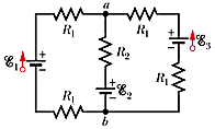
Circuit schematic of a three-loop network with batteries labeled E1, E2 and E3, resistors labeled R1 and R2, and nodes labeled a and b.

Homework Statement


(a) Calculate the current through each ideal battery in Fig. 28-41.
(As a sign convention, assume the currents are "up" through each battery.)


A (I1)
A (I2)
A (I3)

Assume that R1 = 1.5 , R2 = 2.5 , ε1 = 2.0 V, and ε2 = ε3 = 3.5 V.

(b) Calculate Va - Vb


Homework Equations


V=iR


The Attempt at a Solution


I don't know how to approach this problem, use kirchhoffs law?


Yes, Kirchhoff's laws or techniques based upon them are the way to go.


ok so i set up 3 loops and after simplifying i get:

Loop 1(the square on the left):-.6+1.2(i1)= i2
Loop 2(right square): 2.5(i2)=1.5(i3)
loop 3(the whole rectangle): 1.5=-3(i1+i2)

and that i1 = i2+i3


lodovico said:
ok so i set up 3 loops and after simplifying i get:

Loop 1(the square on the left):-.6+1.2(i1)= i2
Loop 2(right square): 2.5(i2)=1.5(i3)
loop 3(the whole rectangle): 1.5=-3(i1+i2)

and that i1 = i2+i3

Check the signs in your Loop 1 equation.

The coefficient of the i3 term in your Loop 2 equation doesn't look right.

Check the signs of the terms in your Loop 3 equation.


ok i just redid my loops I am not sure what is going wrong

1) 2-1.5(i1)-2.5(i2)-3.5-1.5(i1)=0
2) 3.5-2.5(i2)-1.5(i3)-3.5-1.5(i3)=0
3) 2-1.5(i1)-1.5(i3)-3.5-1.5(i3)-1.5(i1)=0

1) -.6-1.2(i1)=i2
2)-.833(i2)=i3
3)-.5-i3=i1


lodovico said:
ok i just redid my loops I am not sure what is going wrong

1) 2-1.5(i1)-2.5(i2)-3.5-1.5(i1)=0
2) 3.5-2.5(i2)-1.5(i3)-3.5-1.5(i3)=0
3) 2-1.5(i1)-1.5(i3)-3.5-1.5(i3)-1.5(i1)=0

1) -.6-1.2(i1)=i2
2)-.833(i2)=i3
3)-.5-i3=i1

Let's gather together the resistors in the branches and redraw the circuit showing the currents (blue) and the potential drops across the resistors (red) caused by those currents. This should make it easier to keep the signs of things straight when you do your "KVL walk" around a loop.
Circuit schematic with three parallel branches between nodes a and b: 3 Ω resistor with 2 V battery, 2.5 Ω resistor with 3.5 V battery, and 3 Ω resistor with 3.5 V battery, with blue currents i1, i2, i3 and red polarity marks on resistors.


See if you can spot any sign issues in your equations.
 
Attachments
  • Circuit schematic of three parallel branches between nodes a and b: left branch 3 Ω resistor with 2 V battery, middle branch 2.5 Ω resistor with 3.5 V battery, right branch 3 Ω resistor with 3.5 V battery. Blue arrows mark currents i1, i2, i3 upward; red polarity signs on resistors.
    Fig2.gif
    1.9 KB · Views: 939


1) -1.5-3(i1)-2.5(i2)=0
2) -2.5(i2)-3(i3)=0
3) -1.5-3(i1)-3(i3)=0

1) 1.5=-3(i1)-2.5(i2)
2)-2.5(i2)=3(i3)
3)1.5=-3(i1)-3(i3)


lodovico said:
1) -1.5-3(i1)-2.5(i2)=0
2) -2.5(i2)-3(i3)=0
3) -1.5-3(i1)-3(i3)=0

1) 1.5=-3(i1)-2.5(i2)
2)-2.5(i2)=3(i3)
3)1.5=-3(i1)-3(i3)

Did you pay attention to the directions of the potential changes on the resistors as you passed over them during your "walks" around the loops? I question the sign you've attributed to the 2.5(i2) term in your first loop equation, and to the 3(i3) terms in equations 2 and 3.

Remember, the polarities of the potential changes on the resistors are fixed by the assumed directions of the currents. You record those potential changes according to the direction you pass through the components as you proceed around the loop.