Finding resistor's voltage with current and voltage sources present

5 replies · 8K views · last reply
JJBladester
Gold Member
Messages
281
Reaction score
2
What is the voltage across R2? You should convert the 4 V source and resistor into a current source as your first step.
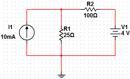
Circuit schematic: current source I1 of 10mA in parallel with R1 25Ω, with R2 100Ω in series with V1 4 V, all joined across the same two nodes.


The first thing I did is create a second current source out of the 4 V voltage source and the series resistor R2. I called it I_2.

I_2 = E/R_2 = 4V/100Ω = 40 mA

This gives us:
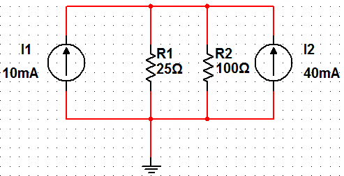
Circuit schematic with a 10mA current source (I1) and a 40mA current source (I2) connected in parallel across two resistors, R1 = 25Ω and R2 = 100Ω, with the bottom rail grounded.


We can combine the parallel current sources I_1 and I_2:

I = I_1 + I_2 = 10 mA + 40 mA = 50 mA
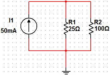
Circuit schematic: a current source labelled I1 50mA in parallel with R1 25Ω and R2 100Ω, all connected to ground.


By the current divider rule,

I_R2 = (R_T*I)/R2 = (20Ω*50mA)/100Ω = 10 mA

V_R2 = I_R2*R2 = 10mA * 100Ω = 1 V

However, when I run a simulation of the original circuit using MultiSim, I get 3 V through R2. Where am I going wrong?
 
JJBladester said:
What is the voltage across R2? You should convert the 4 V source and resistor into a current source as your first step.

Circuit schematic with a 10 mA current source I1 on the left in parallel with R1 25Ω, and R2 100Ω in series with V1 4 V on the right, all connected to ground.


The first thing I did is create a second current source out of the 4 V voltage source and the series resistor R2. I called it I_2.

I_2 = E/R_2 = 4V/100Ω = 40 mA

This gives us:

Circuit schematic with a 10 mA current source I1 and a 40 mA current source I2 on the outer branches, resistors R1 = 25 Ω and R2 = 100 Ω in parallel between them, with the common node connected to ground.


We can combine the parallel current sources I_1 and I_2:

I = I_1 + I_2 = 10 mA + 40 mA = 50 mA

Circuit schematic: a current source labeled I1 = 50mA on the left, in parallel with resistor R1 = 25Ω and resistor R2 = 100Ω, all connected between a top wire and a bottom wire that goes to ground.


By the current divider rule,

I_R2 = (R_T*I)/R2 = (20Ω*50mA)/100Ω = 10 mA

V_R2 = I_R2*R2 = 10mA * 100Ω = 1 V

However, when I run a simulation of the original circuit using MultiSim, I get 3 V through R2. Where am I going wrong?
If you get 3 V across R2 in the original circuit, that means that there voltage dropped across R1 in the original circuit is 1 V, which makes sense.

The difficulty appears to be that you are assuming the resistor, R2 in the original circuit has the same voltage across it as the resistor, R2, in the last two circuits.
 
I'm stuck. I think I understand what you mean that R2 in the new (simplified) circuit cannot be treated the same as R2 in the original circuit. Am I correct up to the point where I found a combined 50 mA current source acting on two parallel resistors R1 and R2?

If so, how do I get back to finding the voltage for R2 in the original circuit.
 
JJBladester said:
I'm stuck. I think I understand what you mean that R2 in the new (simplified) circuit cannot be treated the same as R2 in the original circuit. Am I correct up to the point where I found a combined 50 mA current source acting on two parallel resistors R1 and R2?

If so, how do I get back to finding the voltage for R2 in the original circuit.

Find the voltage across R1 in the simplified circuit. It hasn't been changed. Then use that to find the voltage across R2 in the original circuit.
 
JJBladester said:
We can combine the parallel current sources I_1 and I_2:

I = I_1 + I_2 = 10 mA + 40 mA = 50 mA ✔[/size][/color]

By the current divider rule,

I_R2 = (R_T*I)/R2 = (20Ω*50mA)/100Ω = 10 mA
[strike]There are two mistakes in this line, yet you end up with 10 mA and that's the right answer[/strike]https://www.physicsforums.com/images/icons/icon4.gif
Oops, my mistake. What you are using is not what I think of as current divider rule, but it's okay.
 
Last edited by a moderator:
SammyS said:
Find the voltage across R1 in the simplified circuit. It hasn't been changed. Then use that to find the voltage across R2 in the original circuit.

So I can't use the "new" R2 even though it is the same R2 as before?

Anyway, using your advice to find the voltage across R1 in the simplified circuit, I've found the voltage across R2 using Kirchhoff's Voltage Law on the original circuit:

Hand-drawn circuit schematic with a 10 mA current source I1 on the left, a 25 Ω resistor R1 in the middle branch with voltage V_R1, a 100 Ω resistor R2 on top with voltage V_R2, a voltage source on the right, and a loop current labelled 1.


Using the current divider rule:

[tex]I_{R1}=\frac{(20\Omega )(.05 A)}{(25 \Omega )}=.04A[/tex]

[tex]V_{R1}=\left (I_{R1} \right )\left (R_1 \right )=\left ( .04A \right )\left (25\Omega \right )=1V[/tex]

E - VR2 - VR1 = 0
VR2 = E - VR1 = 4V - 1V = 3V