Help for bending calculation rectangular steel tube

AI Thread Summary
The discussion centers on the structural integrity of a metal preframe for a French window using rectangular steel tubes. The user is evaluating the deflection of the uprights and horizontal beam under load, initially simulating with a 100 x 50 x 3 mm tube and observing a deflection of 19 mm under a 150 kg force. After testing with a larger 120 x 60 x 5 mm tube, the deflection decreased to 27 mm, suggesting limited improvement. Participants emphasize the importance of understanding displacement metrics in FreeCAD and the need for safety considerations regarding load-bearing capacity. The user is considering whether to change the profile for better performance.
chapuis60
Messages
6
Reaction score
1
Hi all

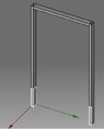
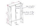
In order to make a metal preframe for a French window as an entrance door, I began to estimate the possibility of building it in rectangular steel tubes of 100 x 50 x 3 mm, laid independently of the walls that could not accept such a load because it was timber framed. The preframe will consist of 2 uprights of 2m80 including 50 cm embedded in a concrete slab and a horizontal beam of 1m30 in the high position. The 2-leaf PVC patio door weighs about 90 kilos.

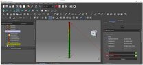
I started to simulate the resistance of the uprights without the horizontal beam under Freecad by imposing a horizontal force of 150 kg, I find a boom of about 19 mm. Could someone confirm this value?

Wouldn't a 100 x 50 UPN or other profile (uneven angle) do the trick?
Thank you.
 

Attachments

  • Capture d’écran 2022-10-24 151634.jpg
    Capture d’écran 2022-10-24 151634.jpg
    13.1 KB · Views: 158
  • Capture d’écran 2022-10-13 171559.jpg
    Capture d’écran 2022-10-13 171559.jpg
    34.8 KB · Views: 123
  • Capture d’écran 2022-10-24 151725.jpg
    Capture d’écran 2022-10-24 151725.jpg
    31.7 KB · Views: 141
Engineering news on Phys.org
Can you share the FreeCAD file or a screenshot showing where/how the beam is supported and loaded in the analysis?
 
We need a sketch showing how it is supported and what loads are applied where. Then we need to know how you modeled it. We also need to know if there are any safety considerations. What happens if the structure is not stiff or strong enough - does the door bind up or does something heavy come crashing down?
 
  • Like
Likes berkeman
Hello, no problem.
I am attachiHelng the simulation files on Freecad with also a UPE of 100x55x3 mm. I did the test with a single upright embedded 40 cm in the concrete and a force of 1500 N located on the edge of the upright. This value may be excessive, but I wanted to take into account the weight of the leaves, especially when the door is open.

Freecad files must be renamed from .txt to .FCStd to read them under the software.
 

Attachments

The analytically calculated deflection is around 37 mm for the beam with the box section. You should use a much denser mesh.
 
So I modified the mesh by taking the max element size to 10 mm. Indeed, the distribution of the effort is not the same, but I find a Displacement magnitude at 37 mm. Did I miss something? I discover Freecad on this domain. I don't really understand the difference between Displacement Magnitude and Displacement X.
 
Files from the simulation :
 

Attachments

  • Paramètres mesh.jpg
    Paramètres mesh.jpg
    19.1 KB · Views: 119
  • Displacement X 72 micro m.jpg
    Displacement X 72 micro m.jpg
    20.5 KB · Views: 127
  • Displacement magnitude 37,80 mm.jpg
    Displacement magnitude 37,80 mm.jpg
    19.5 KB · Views: 123
chapuis60 said:
I don't really understand the difference between Displacement Magnitude and Displacement X.
Displacement magnitude is the resultant displacement calculated from all the displacement vector components. And you can check individual components (X,Y,Z) as well, just make sure that you are checking the right component with respect to the global coordinate system and the way the beam is loaded and deforms. In this case, the beam is bending in Y axis so you should check the Y displacement to find the deflection.
 
Ok, I understand better. I took the hypothesis of a localized force on the upper edge of the vertical rectangular tube by imagining that it is the maximum effort, door closed. When a leaf is open, there will also be forces along the X axis. I have not tested.

I would have to test with a larger tube in 120x60x5 for example.
 
  • #10
Good evening, I did a simulation this time with a 120x60x5 mm tube, I have a 27 mm arrow instead of 37 mm with the 100x50x3 tube. In fact, I just gained only 10mm less on the boom.

I wonder if it is not necessary to change the profile.
 

Attachments

  • Capture d’écran 2022-10-28 201705.jpg
    Capture d’écran 2022-10-28 201705.jpg
    19.6 KB · Views: 122
Back
Top