How Can Imaging Fossil Thin Sections Unlock Microscopic Wonders?

  • Thread starter Thread starter Andy Resnick
  • Start date Start date
  • Tags Tags
    Imaging
Join the discussion
Ask a follow-up here, or get your own question answered by working scientists, mathematicians and engineers — people, not an autocomplete.
Real named experts · corrections over time · the nuance an AI answer skips
22 replies · 5K views
TL;DR
Post your petrographic images!
Sometimes I win at eBay:
1681932901520.png


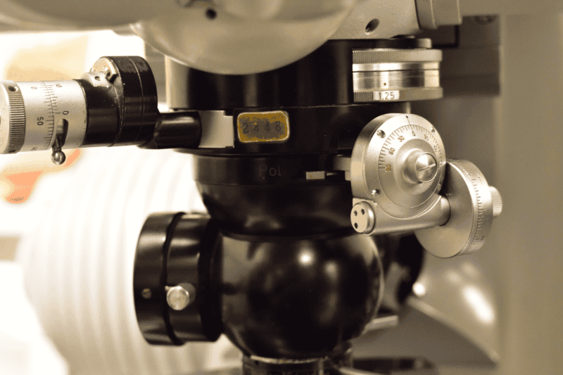
On the right is a Ehringhaus quartz compensator in perfect condition- I believe the seller didn't know what they had, I got it for $200. Now I need to learn how to use it :)

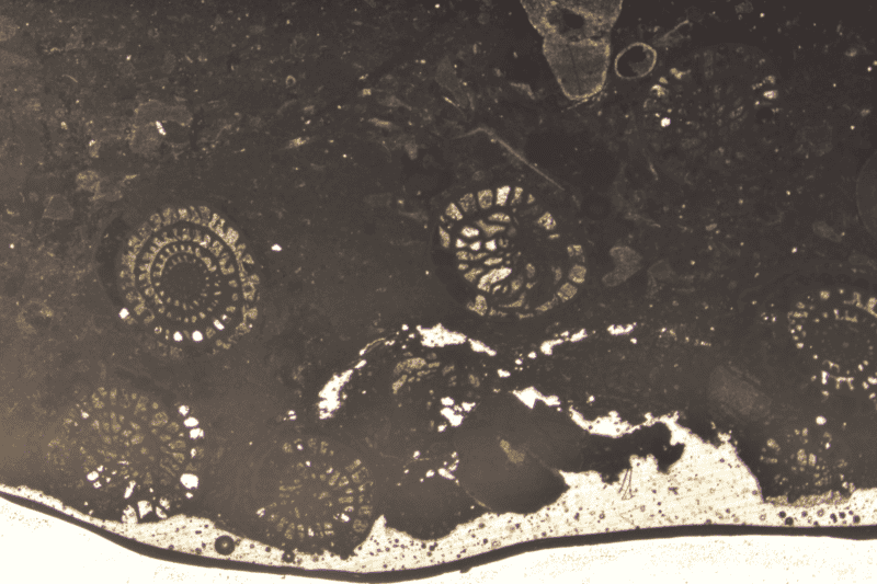
It seems that whatever I decide to learn how to photograph, @davenn has been there already. With his encouragement, I am getting some thin sections fabricated, hopefully I'll have them by this summer. In the meantime, I scored a set of fossil thin sections (at about $5 per section), my suspicion is that they were made by a (grad?) student as part of a course.

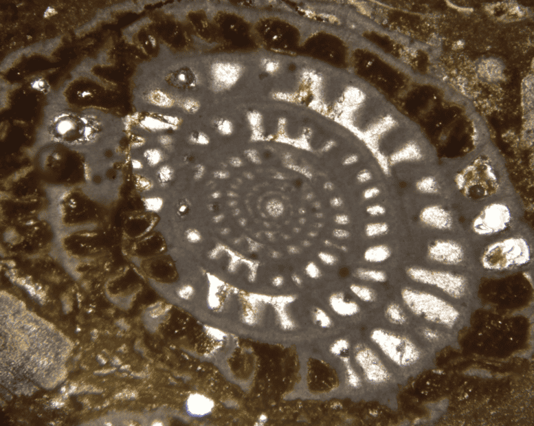
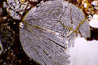
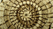
Here's a macro-view, taken with a zoom Luminar, of a sample from the Graford Formation (Upper Pennsylvanian) show some fossils in cross-section:
1681933265280.png


And a closer view at 4X:
1681933294078.png


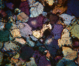
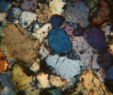
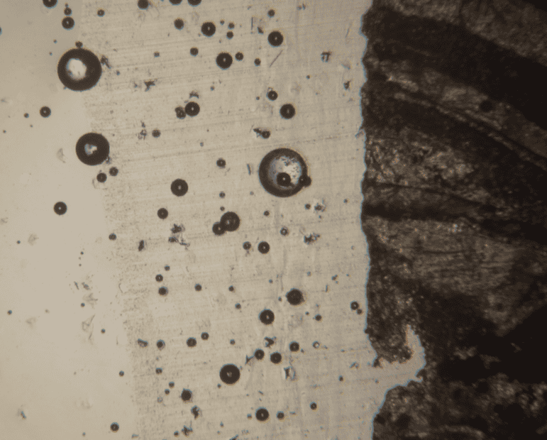
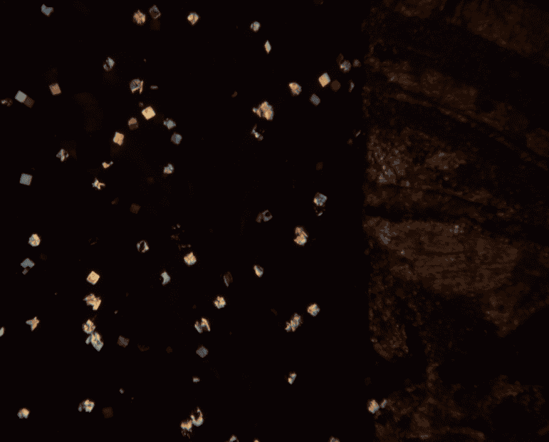
One thing I don't understand are the presence of small flakes of "something", I think part of the sample prep- these are uncovered and non polished sections. The flakes are uniform size, square, and highly birefringent. Two views, one with parallel polarizers and the other with crossed polars:
1681933439509.png


1681933461905.png


continued....
 
Reply
  • Like
  • Wow
  • Love
Likes   Reactions: pinball1970, davenn, Astronuc and 1 other person
Earth sciences news on Phys.org
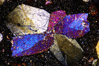
The next sample I worked with is from the Dneister Formation (Devonian)- here's when I start to move beyond 'hey, cool pics!'. Here are a couple grains of something, in two different rotation orientations with respect to the crossed polars at 16X:

1681933786244.png

1681933803498.png


The colors of one grain changes, but not the other....

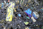
And using the compensator on a cemented sandstone sample from the Crigglestone Rock Formation (Carboniferous) gives the following sequence as the compensator retardation changes from 0 to (I think) +1λ, based on a rotation angle of 30 degrees:
1681934128967.png


1681934148411.png


1681934164072.png


1681934228773.png


Not sure what these minerals are... any guesses?

I tried to get some interference figures, but nothing was 'clean' enough.
 

Attachments

  • 1681934185181.png
    1681934185181.png
    311.2 KB · Views: 177
  • 1681934346450.png
    1681934346450.png
    332.7 KB · Views: 219
Reply
  • Like
  • Love
Likes   Reactions: Rive, davenn, Astronuc and 5 others
Andy Resnick said:
One thing I don't understand are the presence of small flakes of "something", I think part of the sample prep- these are uncovered and non polished sections.
Maybe cubes of crystal grit, (embedded in the Canada balsam cement which has the same RI as the glass slide).
 
I remember the 1970s, when petrology could always be bright and colourful, no need for hallucinogenics then. At the time, I felt the rocks knew more about me, than I did of them. Handheld XRF has ruined that game.
 
Reply
  • Like
Likes   Reactions: Andy Resnick
Andy Resnick said:
The next sample I worked with is from the Dneister Formation (Devonian)- here's when I start to move beyond 'hey, cool pics!'. Here are a couple grains of something, in two different rotation orientations with respect to the crossed polars at 16X:Not sure what these minerals are... any guesses?

I tried to get some interference figures, but nothing was 'clean' enough.
As far as I understand it, these sections are fossiliferous. These sections are usually thicker than petrographic sections, which makes identification of the mineral content far more difficult.
You should try to determine the thickness of your sample. To this end, use a rather highly magnifying objective (40 or 50) and focus on the upper and lower side of your sample. The fine drive should be gauged in mum on your microscope. Take the difference and multiply by the approximate index of refraction of your sample (usually 1.5). You can then determine the maximal interference colours from a Michel Levy chart (https://www.researchgate.net/publication/242341440_extended_chart).
Are these slides covered? Petrographic analysis requires the slides to be grinded (but not polished) and covered, to be able to judge e.g. the "chagrin", which allows for estimation of the index of refraction.
 
Andy, maybe you want to describe your setup more in detail. I would be very interested. These luminars are rather for macrophotography than for microscopy. How did you adapt them to your mic?
 
Here some pictures:
1. Prehnite, Norway
2. Essexite, Kaiserstuhl Volcanoe, Germany
3. Nummulith, Bad Adelholzen, Germany
4. Nummulith, Glauconitic filling after treatment with HCl. Bad Adelholzen
5. Limburgite, Limberg, Germany
6. Chondrite, North Africa

I just realized that the photos are not always shown in the same order. So consider this to be a quiz!
 

Attachments

  • IMG_5428.JPG
    IMG_5428.JPG
    123.6 KB · Views: 167
  • IMG_5551.JPG
    IMG_5551.JPG
    137.1 KB · Views: 164
  • Nummulit1.JPG
    Nummulit1.JPG
    26.3 KB · Views: 181
  • IMG_5056.JPG
    IMG_5056.JPG
    75 KB · Views: 154
  • IMG_5590.JPG
    IMG_5590.JPG
    153 KB · Views: 164
  • IMG_5744.JPG
    IMG_5744.JPG
    129.8 KB · Views: 163
Last edited:
Reply
  • Like
  • Wow
Likes   Reactions: pinball1970 and Rive
DrDu said:
Andy, maybe you want to describe your setup more in detail. I would be very interested. These luminars are rather for macrophotography than for microscopy. How did you adapt them to your mic?
Very lo-tech. I'm using my Ultraphot in 'macro mode'... there don't seem to be any pics I can grab online to show.... here's a couple of images using a 'dummy camera':

1684252290962.png


One polarizer (small, about 40mm diameter) sits below the illuminator, there's a shallow well that can accommodate it. The analyzer is a 6" x 6" sheet of polaroid, placed directly in front of the camera (no lens on the camera)- in the images above, you can see reflections off that polaroid sheet. I first orient the polars by rotating the lower polarizer until extinction is achieved, I can't really rotate the analyzer. Once they are perpendicular, I place the illuminator in position and rotate the sample until I get good colors.
 
Reply
  • Love
  • Like
Likes   Reactions: pinball1970 and DrDu
DrDu said:
Here some pictures:
1. Prehnite, Norway
2. Essexite, Kaiserstuhl Volcanoe, Germany
3. Nummulith, Bad Adelholzen, Germany
4. Nummulith, Glauconitic filling after treatment with HCl. Bad Adelholzen
5. Limburgite, Limberg, Germany
6. Chondrite, North Africa

I just realized that the photos are not always shown in the same order. So consider this to be a quiz!

Nice! What lens did you use for these?
 
Here's a few images of a partially serpentinized olivine phenocryst, from a different sample (not sure what rock type):

DSC_0657 copy.jpeg


A closer view shows some of the reaction-diffusion kinetics resulting in a spatial distribution of magnetite crystals:

DSC_0658 copy.jpeg


The black stripe long the bottom is a magnetite vein where (I think) the reaction initiated, and the upper corner shows some unaltered olivine. The small black dots are magnetite crystals. Here's another example:

DSC_0669 copy.jpeg


Enjoy!
 
Last edited:
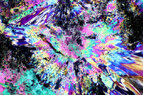
And here's opal, first at 4x: no polarizer, and then crossed polars:

1689618874051.png


1689618894160.png


The colors come from diffraction, not birefringence. Using a 1λ plate turns the field a uniform purple-red color.

To show how opal is a diffractive material, I imaged at 40X, no polarizers, to show the microstructural spheres- opal is a naturally ocurring photonic bandgap material:

1689618954775.png
 
Reply
  • Like
  • Love
Likes   Reactions: DrDu and jim mcnamara