Homework Help Overview
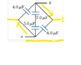
The discussion revolves around determining equivalent capacitance in a complex circuit with multiple capacitors arranged in parallel and some in series. Participants explore the implications of circuit configuration and the behavior of current flow in relation to the arrangement of components.
Discussion Character
- Exploratory, Conceptual clarification, Assumption checking
Approaches and Questions Raised
- Participants discuss the possibility of additional paths in the circuit and question the assumptions about current flow direction. There are suggestions to redraw the circuit for clarity, and some express confusion about the equivalence of different circuit configurations. The role of ideal connecting wires and equipotential points is also examined.
Discussion Status
The discussion is ongoing, with participants providing clarifications and visual aids to enhance understanding. There is a focus on the connectivity of components rather than their geometric arrangement. Some participants have raised questions about color coding and its implications for understanding potential differences in the circuit.
Contextual Notes
Participants are navigating the complexities of circuit analysis, including the treatment of wires as ideal and the implications of moving endpoints in circuit diagrams. There is an emphasis on understanding the potential differences and connectivity in the circuit.