How does a Hills Hoist clothesline mechanism work?

4 replies · 7K views · last reply
TheNarrator
Messages
9
Reaction score
0
Firstly, am struggling to wrap my head around exactly how the mechanism for a traditional 'hills hoist' (as seen below) clothesline functions.
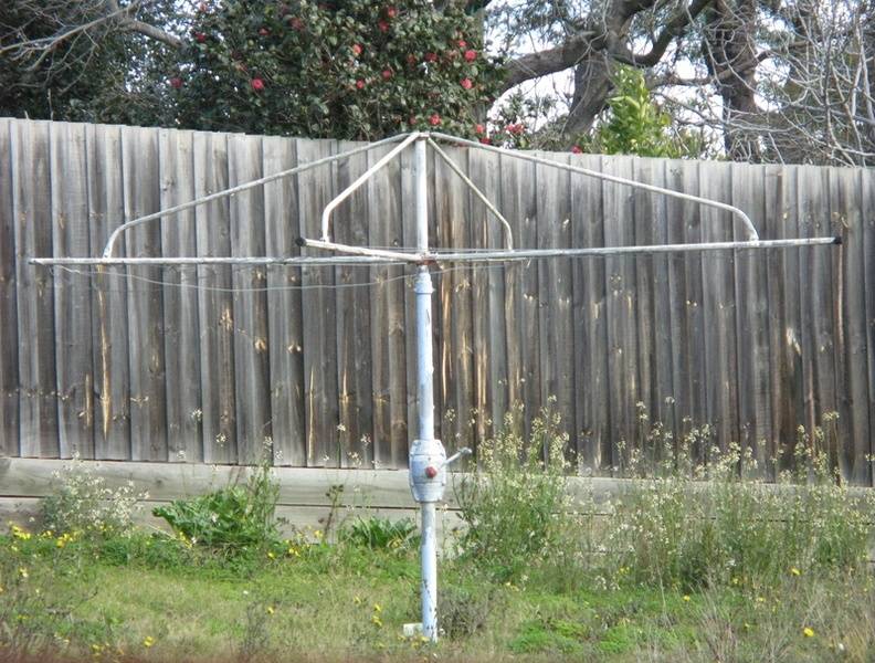
Rotary clothesline with a central vertical pole and a crank housing near its base, with four horizontal arms spread out above, set in a garden in front of a wooden fence.


The handle can be turned in order to raise the clotheslines but from my googling, the mechanism is different to what I was expecting.

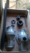
Would be greatly appreciated if someone were able to explain to me how systems such as the ones shown below function.
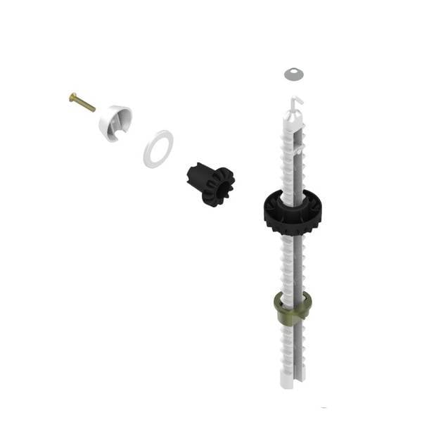
Exploded view of a rotary clothesline winding mechanism: a screw, a white cap, a washer, a black gear-like drive piece, and a long white threaded rod with a black collar and green bushing.

Photo of disassembled gearbox parts on a cardboard box: a long toothed rack bar, two cast metal gear housings, and smaller gears and a shaft, laid out for inspection.


Does the entire handle assembly move along the central threaded rod, pushing up the upper section?

If so is there a way to achieve this with the handle assembly fixed?

Feel like it's probably quite a simple answer but haven't been able to find much specific information on it
 
Last edited by a moderator:
TheNarrator said:
Does the entire handle assembly move along the central threaded rod, pushing up the upper section?

No. In the top image, the only visibly moving parts are the crank handle rotating and everything above 2/3 the height of the fence moving upward (the photo shows it in it's lowermost position).

In your second image:
Only the threaded rod moves up or down,it doesn't rotate, all others parts rotate or are stationary.
The hand crank rotates the LH bevel gear which rotates the RH bevel gear whose internal threading drives the lead screw up or down. The lower brass coloured collar prevents the lead screw from rotating.
 
  • Like
Likes   Reactions: TheNarrator
Thanks for your response.

So that means the handle assembly is fastened to the exterior stationary pole in some way correct?

I need to make a system like this where the threaded rods extends but want it to rotate through 360deg (preferably only once) as it extends. is there a way to achieve this by modifying a hills hoist or am I on the wrong track completely?
 
The reason for lots of turns is: in general mechanical advantage increases as the rate of the extension per turn decreases.

Questions you need to answer:
So - how much extension or retraction is required for one revolution?
Diameter of the central shaft == ?
Mass of the "stuff" or payload at the top of the rod == ?
 
TheNarrator said:
Thanks for your response.

So that means the handle assembly is fastened to the exterior stationary pole in some way correct?
That's right.

I need to make a system like this where the threaded rods extends but want it to rotate through 360deg (preferably only once) as it extends. is there a way to achieve this by modifying a hills hoist or am I on the wrong track completely?
If you replaced the lead screw with one something like this:
3D CAD render of a long, tall helical screw with a square-profile thread, shown standing vertically against a plain grey background.


It'd rotate once per full height extension. Though, that'd be very difficult/expensive to make.
If you give us details of what you're trying to do we may have better suggestions.
 
  • Like
Likes   Reactions: jim mcnamara