chessguy103
- 13
- 3
- TL;DR
- How can I take a 2D pressure problem and then it into a 1D beam problem?
Hi,
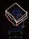
Forgive me for the crowded drawing, but please reference the attached screenshot. Let’s say I have 2 plates bolted together by some bolts (red), and on the inside is a pressure w pushing the top plate up, in psi (lb/in^2). In order to get an estimate for the maximum distance between bolts, I want to take the circled part and treat it as a 1D problem.
My question is, how do I take that w, and convert it into q in lb/in?
Thanks