Mesh Equations and Polarity in Coupled Circuits

7 replies · 2K views · last reply
ranju
Messages
221
Reaction score
3

Homework Statement


In the given attachment (supply has voltage v(t) , ) we have to write mesh equations .I am not getting how to decide the polarity of voltage across inductor ?

Homework Equations

The Attempt at a Solution


There's nothing much to do.. The only thing I am doubtful about is the polarity.
 
Attachments
  • Hand-drawn circuit schematic of a magnetically coupled network with resistors R1, R2 and R3, inductors L1, L2 and L3, and a voltage source on the left, with dot markings on the coupled coils.
    IMG_20141001_184550.jpg
    43.1 KB · Views: 537
Last edited by a moderator:
You're writing mesh equations so you have assumed the directions of loop currents. Use those directions along with the dot notation convention to determine the polarities of the voltages induced via mutual inductance.
 
Is the convention like this ?? : If a current enters (leaves) the dotted terminal of one coil, the reference polarity of the mutual voltage in the second coil is positive (negative) at the dotted terminal of the second coil.
 
ranju said:
Is the convention like this ?? : If a current enters (leaves) the dotted terminal of one coil, the reference polarity of the mutual voltage in the second coil is positive (negative) at the dotted terminal of the second coil.
Yes, that's it.
 
So how we will proceed.. I mean.. we should just consider one coil as the reference i.e. as current in L1 is leaving the coil then the polarity of voltages of L2 & L3 will be negative at the dotted terminal..?? then with which coil reference we will decide polarity of L1..??
 
ranju said:
So how we will proceed.. I mean.. we should just consider one coil as the reference i.e. as current in L1 is leaving the coil then the polarity of voltages of L2 & L3 will be negative at the dotted terminal..?? then with which coil reference we will decide polarity of L1..??
You don't have to decide the overall polarity of net potentials beforehand; let the math take care of sorting that out for you. It's like mesh currents, you make an assumption about directions and then do the math. Some will turn out positive and others negative, the math sorting it out.

For mutual inductors you may find it handy to insert a voltage source in series with each inductor. Orient them so that they would produce a current out the dot on their inductor. These sources are placeholders for where you'll gather together the induced voltages from the other inductors. So you'll see that the original inductors remain in the circuit and are treated as typical isolated components and the new voltage sources take on the coupling effects.
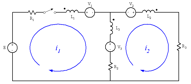
Circuit schematic with two mesh loops i1 and i2 containing series resistors R1, R2, R3, inductors L1, L2, L3 with dot polarity markings, voltage sources E, V1, V2, V3, and a switch.


Now you can write mesh (or nodal) equations using these components easily enough. To work out the "value" of a given voltage source, look at the currents flowing through the other coupled inductors. If a current flows into a dot then add a positive term to the voltage for that inductor. If the current flows out of the dot then add a negative term. The terms are composed of the mutual inductance between the two inductors in question multiplied by the time derivative of the current in question (or if you're using the Laplace notation,##sM_{mn} I_n##, with the "s" operator implying the derivative).

For a concrete example, suppose the mutual inductances between the inductors in your circuit are ##M_{12},M_{23}, M_{13}##. For V3 you need to consider terms due to the currents flowing through ##L_1## and ##L_2##. In the figure, ##i_1## is flowing into the dot on ##L_1## so it's contributing term will be positive: ##+s M_{13} i_1##. On the other hand, ##i_2## flows out of the dot on ##L_2##, so it contributes a negative term: ##-s M_{23} i_2##. Thus:
$$V_3 = sM_{13} i_1 - sM_{23} i_2$$
Do the same for the other sources. Take note that the current flowing through ##L_3## is ##i_1 - i_2##, so the terms contributed to ##V_1## and ##V_2## have that as their current!
 
gneill said:
Orient them so that they would produce a current out the dot on their inductor.
but according to the polarity of voltage sources it seems as is current is entering the dot.!
 
ranju said:
but according to the polarity of voltage sources it seems as is current is entering the dot.!
I'm not sure why you'd say that. Take a look at, say, V2 paired with L2:

Circuit schematic of a voltage source V2 with a plus sign on its right side in series with inductor L2, which has a dot marking its right terminal; a blue arrow points right from the source and a dotted arrow points right past the dot, with the label 'Polarity of the potential V2 would want to drive current in the direction "out-of-the-dot"'.

V2's potential would like to drive current in the direction through L2 and out of its dot.