Question about the Redistribution of Charges

AI Thread Summary
The discussion centers on the interpretation of an equation related to charge redistribution in capacitors, specifically questioning the representation of charge stored in capacitor CN. The author suggests that the equation should reflect the difference voltage across CN rather than simply using Vref. A simulation involving two capacitors, C1 and C2, was conducted to validate this perspective. Participants also addressed issues with image clarity and forum usage, emphasizing the need for better visuals to support the discussion. Overall, the conversation highlights a technical disagreement regarding the physics of capacitor charge calculations.
Virmus00
Messages
3
Reaction score
0
TL;DR Summary
Redistribution of charge principal : How does the negative charge Q redistribute after reconnecting it to a positive voltage Vdd=5V?
Hi folks,
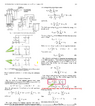
I was trying to understand how the author get the equation (10) that you see in the highlighted page where it is written Vref*CN represent the charge stored within CN which I do not agree for the moment.
so I did a small simulation whith two capacitors C1=2uF and C2=3uF to check if I am right ,I feel like I am right but not the author!!! link to the experiments: two caps charge and discharge
if it was me I would write in the first term of the equation (10) not Vref but [1-CN/Ctotal]*Vref because the charge created by the Cn in Fig 2 (c) is the difference voltage across the CN multiplied by CN!!!!
please help to understand the physics of what is going on at electron level?

redistribution discharge.png
 
Last edited by a moderator:
Engineering news on Phys.org
Virmus00 said:
Sorry my bad. i want to edit/delete it, but I could not find any way to do it like in other forums? is there a guide for how to use it?
You can edit original post only for a limited time. Please add a better image in a reply and moderators will do some cleaning.
 
  • Like
Likes Virmus00 and Steve4Physics
Here it the picture, hopefully it is more clear.

Seems the forums always reduce the quality of the image to reduce the size!!!
 

Attachments

  • chargeredistribution.png
    chargeredistribution.png
    51.8 KB · Views: 43
  • charge2.jpg
    charge2.jpg
    49.7 KB · Views: 36
I have recently moved into a new (rather ancient) house and had a few trips of my Residual Current breaker. I dug out my old Socket tester which tell me the three pins are correct. But then the Red warning light tells me my socket(s) fail the loop test. I never had this before but my last house had an overhead supply with no Earth from the company. The tester said "get this checked" and the man said the (high but not ridiculous) earth resistance was acceptable. I stuck a new copper earth...
Thread 'Electromagnet magnetic field issue'
Hi Guys We are a bunch a mechanical engineers trying to build a simple electromagnet. Our design is based on a very similar magnet. However, our version is about 10 times less magnetic and we are wondering why. Our coil has exactly same length, same number of layers and turns. What is possibly wrong? PIN and bracket are made of iron and are in electrical contact, exactly like the reference design. Any help will be appreciated. Thanks. edit: even same wire diameter and coil was wounded by a...
Thread 'Beauty of old electrical and measuring things, etc.'
Even as a kid, I saw beauty in old devices. That made me want to understand how they worked. I had lots of old things that I keep and now reviving. Old things need to work to see the beauty. Here's what I've done so far. Two views of the gadgets shelves and my small work space: Here's a close up look at the meters, gauges and other measuring things: This is what I think of as surface-mount electrical components and wiring. The components are very old and shows how...

Similar threads

Replies
6
Views
187
Replies
2
Views
2K
Replies
1
Views
2K
Replies
4
Views
3K
Replies
14
Views
3K
Replies
19
Views
4K
Replies
1
Views
1K
Replies
22
Views
5K
Back
Top