Rotation and spring force exercise

Join the discussion
Ask a follow-up here, or get your own question answered by working scientists, mathematicians and engineers — people, not an autocomplete.
Real named experts · corrections over time · the nuance an AI answer skips
16 replies · 2K views
Hajarmq
Messages
8
Reaction score
1
Summary:: Calculating the inclination angle

A stick is on two springs with spring constants D1=500N/m and D2=300N/m. Consider the stick is without mass and can rotate around the point E, which is distant from spring 1 with 0,1m and from spring 2 with 0,8m. A force F=100N pulls the stick up. (sketch below)
a) Calculate the distance by which each spring will be stretched.
Here i got x1= 0,177m and x2= 0,037m
b) calculate the inclination angle (see sketch)

Do you have any idea how i can calculate the angle? A detailed answer would be very much appreciated.

[Mentor Note -- thread moved from the technical forums, so no Template is shown]
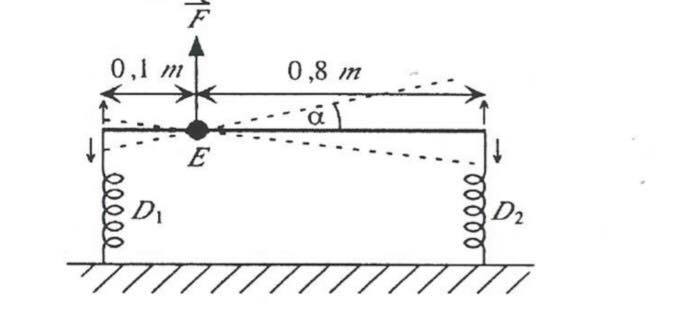
80498195_586699238747720_570101963027382272_n.jpg
 
Last edited by a moderator:
Physics news on Phys.org
Welcome to the PF. :smile:
Hajarmq said:
Do you have any idea how i can calculate the angle? A detailed answer would be very much appreciated.
Start by drawing a free body diagram (FBD) of the stick, and then use the fact that the system is stationary (stick is not moving). What can you say about the sums of the forces and moments in such a situation?
 
It is what I used for calculating the stretch-distances. However, for the angle, i should figure out some height combined with some horizontal distance and use the sine or tangent function on some triangle. This is where i am confused, what height and horizontal distance to consider and why?

Thank you for your answer.
 
Hajarmq said:
It is what I used for calculating the stretch-distances. However, for the angle, i should figure out some height combined with some horizontal distance and use the sine or tangent function on some triangle. This is where i am confused, what height and horizontal distance to consider and why?

Thank you for your answer.

What about taking moments about a suitable point?
 
PeroK said:
What about taking moments about a suitable point?

I still cannot establish a relationship between the moments and the angle. Maybe another hint?
 
Hajarmq said:
I still cannot establish a relationship between the moments and the angle. Maybe another hint?
Can you please show us your FBD and sum of forces and moments equations? You should take into account that the springs are no longer vertical in the final position...
 
berkeman said:
Can you please show us your FBD and sum of forces and moments equations? You should take into account that the springs are no longer vertical in the final position...
78947585_2444498442470190_1114107039044337664_n[1].jpg


F1 and F2 being the amplitudes of each force
 
berkeman said:
You should take into account that the springs are no longer vertical in the final position...
It is not possible to take that into account because we do not know the relaxed lengths. Just have to assume they are much longer than the difference in extensions.
 
  • Like
Likes   Reactions: berkeman
haruspex said:
It might help you to draw a second, simpler, diagram, just showing the rod at an angle and the displacements you found for its ends.

79746874_486934008605064_4796174431661588480_n.jpg


does this make sense? if it does, i can't conclude what the height h is. I am tempted to say its the difference of the two extensions, but i can't really see why.
 
haruspex said:
It is not possible to take that into account because we do not know the relaxed lengths. Just have to assume they are much longer than the difference in extensions.
You mean the drawing in the problem statement is not to scale? :wink:
 
Hajarmq said:
View attachment 254052

does this make sense? if it does, i can't conclude what the height h is. I am tempted to say its the difference of the two extensions, but i can't really see why.
No, the diagram is wrong. (Is that "x3"? What is that?)
You found two extensions, both positive. Draw the initial position horizontal, the two extensions and the final position. But note that the extensions will be heights vertically above the initial position of the rod, not distances from the endpoints in its initial position.
 
haruspex said:
No, the diagram is wrong. (Is that "x3"? What is that?)
You found two extensions, both positive. Draw the initial position horizontal, the two extensions and the final position. But note that the extensions will be heights vertically above the initial position of the rod, not distances from the endpoints in its initial position.

9556740F-4A28-456E-8E03-257823AF1351.jpeg

How to draw the final position? Joining which points?

(it was x1)
 
Hajarmq said:
View attachment 254053
How to draw the final position? Joining which points?

(it was x1)
One end has moved up x1, the other up x2, so which two points do you think?
And as I implied, you should not take the "original position" as representing the whole bar. It only represents the height the bar was at. You need to set the distance between the two displacements in the diagram to match up with the final position.
 
You have calculated the displacements (approximately in the assumption that the displacements and forces are purely vertical). Why not check and see if that assumption is valid? Taking the difference in the displacements as the vertical component and the 0.9 m length of the stick as the hypotenuse, what is the horizontal distance? Is it enough different from the 0.9 m length of the stick to make you concerned about the approximation of vertical displacement? I think you will find that the approximation of vertical displacement is pretty good and you can use that cheat for this problem.

However, it is enough different from the stick length that you might like to try and do it more rigorously. I agree that a precise solution becomes tricky. I believe the correct approach is to assign coordinates in two dimensions to the start and end locations of the two ends of the sticks. Write down every relation you can state. This includes that the distance between the final points must be 0.9 m. It also includes accounting for the angle of the spring force using an unknown initial spring length. Then solve the simultaneous equations.

I have not yet determined if there are enough relations to work around the additional unknown of the initial spring length, but I’m not sure yet that it can’t be done.
 
Cutter Ketch said:
Is it enough different from the 0.9 m length of the stick to make you concerned about the approximation of vertical displacement?
As I noted, we are not told the initial lengths of the springs. The longer they are, the closer the springs approximate vertical in the stretched arrangement. Thus, we can take the displacements as not being from the original positions of the bar's ends but from points vertically below where the ends are after the force is applied.
How much closer that makes them is immaterial in regards precision. Just take the new position of the bar as the hypotenuse, as you say.
The slight imprecision is only in the fact that the springs will not be quite vertical, so the forces not quite parallel, etc.