A SiC Vertical MOSFET channel length modulation

  • Thread starter Thread starter bonkgeek
  • Start date Start date
Click For Summary
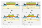
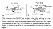
The discussion focuses on the representation of channel length modulation in vertical MOSFETs, particularly how increased drain voltage affects performance. Unlike lateral MOSFETs, vertical MOSFETs have the drain positioned away from the channel, which influences current flow and pinch-off behavior. The speaker presents a vertical MOSFET design, highlighting its unique geometry where current flows vertically from source to drain. Vertical MOSFETs are primarily utilized in SiC power applications due to their superior voltage withstand capabilities. Understanding these differences is crucial for effective application in power electronics.
bonkgeek
Messages
2
Reaction score
3
Hello , Thank you readind me
I wonder how to represent the reduction in channel length(pinch off seen in lateral MOSFET) for vertical mosfets due to the increase in drain voltage because the drain is at the back, away from the creation of the channel position.
 

Attachments

Physics news on Phys.org
Welcome to PF.

Your diagrams only seem to show lateral MOSFETs. Can you show a typical vertical MOSFET geometry and say where it is used? I have not used them yet.
 
Thanks
I am presenting a vertical MOSFET, where the drain is situated in a different plane compared to the source and gate. In this configuration, the current flows vertically from the source to the drain.
This design contrasts with the lateral MOSFET, which you can learn more about by referring to examples available HERE https://www.mks.com/n/mosfet-physics.
Vertical MOSFETs are predominantly used in SiC power MOSFETs, as their vertical structure enables the component to exhibit strong voltage withstand capability.
 

Attachments

  • LATERAL MOSFET.PNG
    LATERAL MOSFET.PNG
    52.7 KB · Views: 124
  • lateral vs vertical.PNG
    lateral vs vertical.PNG
    35.9 KB · Views: 116
I'm setting up an analog power supply. I have the transformer bridge and filter capacitors so far. The transformer puts out 30 volts. I am currently using two parallel power transistors and a variable resistor to set the output. It also has a meter to monitor voltage. The question is this. How do I set up a single transistor to remove whats left of the ripple after the filter capacitors. It has to vary along with the control transistors to be constant in its ripple removing. The bases of the...

Similar threads

  • · Replies 4 ·
Replies
4
Views
4K
  • · Replies 4 ·
Replies
4
Views
4K
  • · Replies 3 ·
Replies
3
Views
18K
  • · Replies 3 ·
Replies
3
Views
22K
  • · Replies 1 ·
Replies
1
Views
18K
Replies
1
Views
2K
Replies
7
Views
3K
  • · Replies 1 ·
Replies
1
Views
4K
  • · Replies 13 ·
Replies
13
Views
3K
Replies
4
Views
8K