soul_syrup
- 1
- 0
- TL;DR
- can someone help me with this circuitry? I am not an electrical engineer
can someone help me with this circuitry? I am not an electrical engineer
I'm working on a brain/organoid computer interface system, and am trying to find out if the modules in the design will connect properly to eachother, and within the system. the system will be using I2S
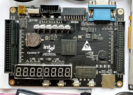
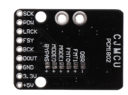
how do we connect the cyclone IV fpga, using I2S, to the PCM1802 module?
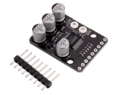
how do we connect the cyclone IV fpga, using I2S, to the CS4344 module?
images:
fpga board
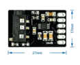
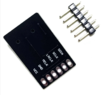
PCM1802 module connectors
PCM1802 module connectors
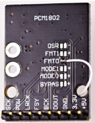
PCM1802 module top view
CS4344 module connectors
CS4344 module connectors
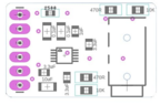
CS4344 module schematic
here is the documentation, along with some other links: https://github.com/Unlimited-Resear...V0.9/BCI-V.09/V0.9.1/BCI_V0.9.1_documentation
I'm working on a brain/organoid computer interface system, and am trying to find out if the modules in the design will connect properly to eachother, and within the system. the system will be using I2S
how do we connect the cyclone IV fpga, using I2S, to the PCM1802 module?
how do we connect the cyclone IV fpga, using I2S, to the CS4344 module?
images:
fpga board
PCM1802 module connectors
PCM1802 module connectors
PCM1802 module top view
CS4344 module connectors
CS4344 module connectors
CS4344 module schematic
here is the documentation, along with some other links: https://github.com/Unlimited-Resear...V0.9/BCI-V.09/V0.9.1/BCI_V0.9.1_documentation
Attachments
-
 Screenshot from 2023-11-10 18-34-14.png139.1 KB · Views: 104
 -
 Screenshot from 2023-11-10 17-02-49.png53.6 KB · Views: 112
 -
 Screenshot from 2023-11-10 17-04-02.png77.2 KB · Views: 102
 -
 Screenshot from 2023-11-10 17-03-40.png50.5 KB · Views: 123
 -
 Screenshot from 2023-11-10 17-23-03.png68 KB · Views: 121
 -
 Screenshot from 2023-11-10 17-21-16.png45 KB · Views: 118
 -
 Screenshot from 2023-11-10 17-19-28.png20.2 KB · Views: 122