Traffic simulation : directed graph including specific rules

  • Context: Undergrad 
  • Thread starter Thread starter Guitz
  • Start date Start date
Join the discussion
Ask a follow-up here, or get your own question answered by working scientists, mathematicians and engineers — people, not an autocomplete.
Real named experts · corrections over time · the nuance an AI answer skips
5 replies · 2K views
Guitz
Messages
22
Reaction score
8
Hi all,

I'm trying to use a directed graph for a traffic simulation program.

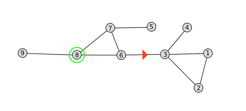
This is an example of a simplified graph :
graph.gif


The red triangle is the position and orientation of the car. The green circle is the destination node.

I wish to prohibit a U-turn on a bend and a crossroads but I authorize it on a dead end (node 4).

The array of nodes (3, 6, 8) is therefore prohibited.
Likewise (3, 1, 3, 6, 8) is forbidden.
On the other hand, (3, 1, 2, 3, 6, 8) and (3, 4, 3, 6, 8) are allowed. The latter being the shortest path.

How please modify the data structure of my graph and the A* (or Dijkstra's) algorithm to achieve my goals?

Thanks
 
Last edited:
Mathematics news on Phys.org
Your search algorithm must exclude the previous node from the nodes to traverse next, unless its the only option.

If a search algorithm marks nodes as allread visted (to abort subsequent longer paths), then you must refine this flag to encode from which node it has already been entered.

Did you really not find any code online for this?
 
Last edited:
I would probably also consider changing the algorithm to adjust for the need at hand, but in case you are somehow required to use a "standard" algorithm unchanged you can perhaps consider to generate a new directed graph from your undirected graph such that the two travel directions on each edge is transformed into a node and these nodes are then connected with directed edges representing valid ways through an intersection or end-point.

This should be possible to do in a fairly mechanic way. For example, the sub-graph from your nodes 1, 2 and 3 you would add the nodes and transitions (1-2) -> (2-3) -> (3-1) and (3-2) -> (2-1) -> (1-3), that is two isolated cycles. Adding your node 4 to this would then add nodes (3-4) and (4-3) along with the transitions {(1-3), (2-3)} -> (3-4) -> (4-3) -> {(3-1), (3-2)}, and so forth.

Old suggestion that was only half baked:
Perhaps it is possible to transform your problem into a directed graph where your original nodes with more than one edge is replaced by two nodes, each with directed edges in relevant directions?
 
Last edited:
Reply
  • Like
Likes   Reactions: Guitz and FactChecker
thanks a lot for your replies
 
Reply
  • Like
Likes   Reactions: berkeman
A.T. said:
Did you really not find any code online for this?
Unfortunately no