Discussion Overview
The discussion revolves around troubleshooting the k_eff value for a space reactor core modeled using MCNP. Participants are examining geometry, material properties, and code adjustments to align their results with expected values. The focus includes technical aspects of reactor modeling, material composition, and computational methods.
Discussion Character
- Technical explanation
- Debate/contested
- Mathematical reasoning
Main Points Raised
- One participant reports a k_eff of 1.4, significantly higher than the expected 1.003, and seeks help in identifying potential mistakes in their code.
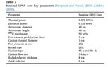
- Another participant suggests that an excess reactivity of 3000 pcm corresponds to a k_eff of around 1.03, noting the fuel composition of graphite with 45% vol UO2 BISO particles.
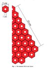
- Concerns are raised about the method of defining the core geometry, with suggestions to abandon the segment method in favor of a lattice definition.
- Participants discuss the importance of correctly calculating atomic ratios and densities, with one noting that using 45% carbon instead of UO2 may have contributed to the high k_eff value.
- One participant mentions a typo in the code that could affect results and discusses the appropriate density for reactor-grade graphite.
- Another participant describes adjustments made to the input file, including flipping surfaces and correcting rod counts, while expressing uncertainty about the accuracy of their material values.
- There is a suggestion to redefine the void cell to encompass all non-active areas, which may help in achieving a more accurate simulation.
- One participant shares a paper related to the reactor technology, indicating potential sources for further information on the core design.
- Another participant expresses uncertainty about modifying the code to change materials in the core perimeter and seeks guidance on this adjustment.
Areas of Agreement / Disagreement
Participants express various viewpoints on the modeling techniques and material properties, with no clear consensus reached on the best approach or the accuracy of the current models. Multiple competing views on the correct definitions and calculations remain evident throughout the discussion.
Contextual Notes
Participants highlight limitations in their models, including potential errors in atomic ratios, density values, and the definition of geometry. There are unresolved issues regarding the correct representation of the reactor core and the implications of various adjustments made to the input files.
Who May Find This Useful
Individuals interested in reactor physics, computational modeling, and those working with MCNP in nuclear engineering contexts may find this discussion relevant.