Rapier
- 83
- 0
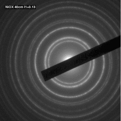
Ok, so we were doing TEM and at the end we were looking at calibration patterns and I'm preparing the presentation and I am writing the intro but I realized I'm not sure why the calibration pattern looks like concentric circles.
I believe it is because we are scanning the beam across the sample at different angles and this is causing the concentric ring pattern.
This is NiOX
 .
.
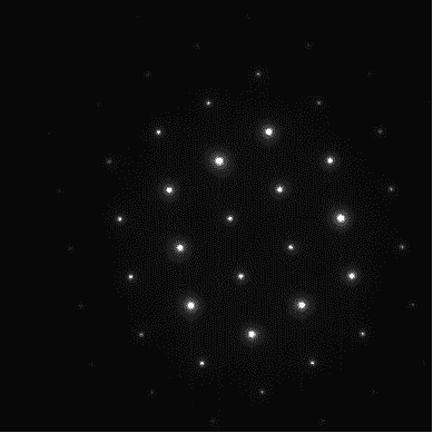
In this second one I'm not quite sure why we don't get concentric rings but just spots. I know that those spots are the locations of the molecules in our crystalline matrix, but I don't get why it's circles in the first and dots in the second. The manual that we used is rather unhelpful in explaining why. In a lot of cases the manual walked us through the steps but didn't really explain why we were doing what we were doing.
Please help!
This is SiGe
 .
.
The presentation is mostly done but I'm just tweaking and want to get the intro for this section done and I'm short on time. Thanks! :)
I believe it is because we are scanning the beam across the sample at different angles and this is causing the concentric ring pattern.
This is NiOX
In this second one I'm not quite sure why we don't get concentric rings but just spots. I know that those spots are the locations of the molecules in our crystalline matrix, but I don't get why it's circles in the first and dots in the second. The manual that we used is rather unhelpful in explaining why. In a lot of cases the manual walked us through the steps but didn't really explain why we were doing what we were doing.
Please help!
This is SiGe
The presentation is mostly done but I'm just tweaking and want to get the intro for this section done and I'm short on time. Thanks! :)