What is the voltage across the resistor in this AC circuit problem?

  • Thread starter Thread starter Ackbach
  • Start date Start date
  • Tags Tags
    2015
Click For Summary
SUMMARY

The voltage across the resistor in the given AC circuit can be calculated using the parameters provided: R1 = 1×10⁶ Ω, C1 = 1×10⁻⁹ F, L1 = 1×10⁻³ H, and the voltage source V1(t) = 120 cos(120 π t) V. The solution involves applying Kirchhoff's laws and analyzing the impedance of the circuit components. The final expression for the voltage across the resistor as a function of time is derived from the circuit's total impedance and the current flowing through it.

PREREQUISITES
  • Understanding of AC circuit analysis
  • Knowledge of Kirchhoff's laws
  • Familiarity with impedance calculations for resistors, capacitors, and inductors
  • Basic proficiency in solving differential equations
NEXT STEPS
  • Study AC circuit analysis techniques
  • Learn about calculating impedance in RLC circuits
  • Explore the application of Kirchhoff's laws in circuit analysis
  • Review differential equations related to electrical circuits
USEFUL FOR

Electrical engineering students, circuit designers, and anyone involved in analyzing AC circuits will benefit from this discussion.

Ackbach
Gold Member
MHB
Messages
4,148
Reaction score
94
Here is this week's University POTW.

-----

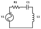
Refer to the following figure:

https://www.physicsforums.com/attachments/3820._xfImport

Given that $R1=1\times 10^6 \, \Omega$, $C1=1\times 10^{-9} \, \text{F}$, and $L1=1\times 10^{-3}\,\text{H}$, and that $V1(t)=120 \cos(120 \pi t)\,\text{V}$, find the voltage across the resistor as a function of time.

-----

Remember to read the http://www.mathhelpboards.com/showthread.php?772-Problem-of-the-Week-%28POTW%29-Procedure-and-Guidelines to find out how to http://www.mathhelpboards.com/forms.php?do=form&fid=2!
 

Attachments

  • MHB-POTW-146-RLC Circuit.png
    MHB-POTW-146-RLC Circuit.png
    1.1 KB · Views: 119
Physics news on Phys.org
An honorable mention goes to topsquark, who provided some comments about the statement of the problem. I stand by the original problem statement, though. Here is my solution:

Converting to the phasor domain, the voltage is $120\angle 0$, the resistor impedance is $1\text{E6}$, the capacitor impedance is
$$\frac{1}{j\omega C}=\frac{1}{j(120\pi)(1\text{E-9})},$$
and the inductor impedance is $j\omega L=j(120\pi)(1\text{E-3})$. Finding the equivalent impedance involves summing the three impedances. This yields
$$Z_{\text{eq}}=2.835\text{E6} \angle -69.344^{\circ}.$$
Next we find the current phasor by dividing the voltage phasor by the equivalent impedance:
$$I=\frac{V}{Z_{\text{eq}}}=4.233\text{E-5} \angle 69.344^{\circ}.$$
Finally, we may compute the voltage phasor across the resistor by using Ohm's law again:
$$V_{R}=IR=(4.233\text{E-5} \angle 69.344^{\circ})(1\text{E6})
=(4.233\text{E1})\angle 69.344^{\circ}
=42.33 \cos(120\pi t+69.344^{\circ}).$$
 

Similar threads

  • · Replies 1 ·
Replies
1
Views
2K
  • · Replies 1 ·
Replies
1
Views
1K
  • · Replies 1 ·
Replies
1
Views
1K
  • · Replies 1 ·
Replies
1
Views
1K
Replies
1
Views
2K
  • · Replies 1 ·
Replies
1
Views
5K
  • · Replies 1 ·
Replies
1
Views
2K
  • · Replies 1 ·
Replies
1
Views
3K
  • · Replies 1 ·
Replies
1
Views
2K
  • · Replies 1 ·
Replies
1
Views
2K