whatsap45
- 5
- 0
1. As compared to the circuit as shown in the figure, i applied KCL in the circuit and still couldn't get the right Ic current at the collector as shown in the simulation.
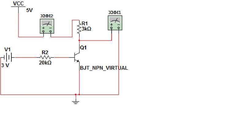
2. The IC current for XMM2 is 1.64mA but i got 22.12mA instead in my calculation. (I'm using the Ic=βIb where β=175 for the solution.)
3. Ib= Vcc-Vbe/20k Ib=3-0.7/20k Ib=0.115mA Ic=Ib (175) Ic=22.12mA
Any idea? Somehow, i need to explain it in my discussion for my report. I screwed up with the calculation and i have no idea of explaining the reason why Vce is approximately equal to 0 when there is a Ib current due to Vb voltage at its base.
More info, XMM1 shows the voltage of 77.205mV...
2. The IC current for XMM2 is 1.64mA but i got 22.12mA instead in my calculation. (I'm using the Ic=βIb where β=175 for the solution.)
3. Ib= Vcc-Vbe/20k Ib=3-0.7/20k Ib=0.115mA Ic=Ib (175) Ic=22.12mA
Any idea? Somehow, i need to explain it in my discussion for my report. I screwed up with the calculation and i have no idea of explaining the reason why Vce is approximately equal to 0 when there is a Ib current due to Vb voltage at its base.
More info, XMM1 shows the voltage of 77.205mV...