Why does point A experience compression in a loaded crankshaft?

Join the discussion
Registration is free. Ask a follow-up in this thread, or start your own.
7 replies · 2K views
yonese
Messages
15
Reaction score
1
Summary:: I'm stuck on a year 2 mechanics question. I have this simplified crankshaft with a load P at the end. The solutions to the exercise have said that point A is in compression due to a bending moment but I don't understand why that is. The solutions and my calculations have both come out with positive values for the stress at A, and I thought a positive value for stress = tension, negative = compression.
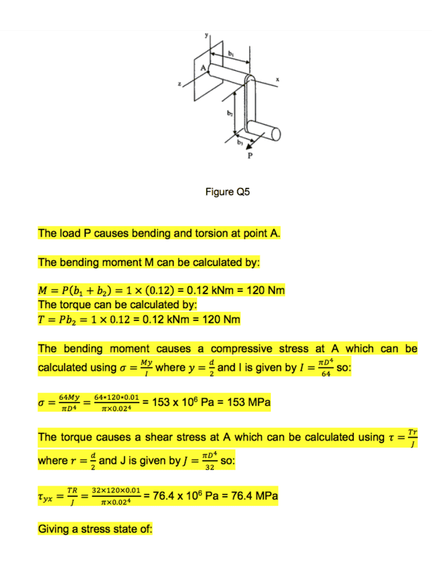
Screen Shot 2020-12-20 at 16.19.32.png
 

Attachments

  • Screen Shot 2020-12-19 at 14.59.13.png
    Screen Shot 2020-12-19 at 14.59.13.png
    15.3 KB · Views: 227
  • Screen Shot 2020-12-20 at 16.19.32.png
    Screen Shot 2020-12-20 at 16.19.32.png
    34.5 KB · Views: 233
Physics news on Phys.org
The moments (and forces) have directions that can be determined by the sign.

But for a beam in bending, you have the following situation:

image002.gif

beam_bending.png

When under the bending moment ##M##, the point on the convex portion (bottom) of the beam is in tension, but the concave portion (top) of the beam is in compression. The point A of your crankshaft would be in the concave portion.
 
  • Like
  • Informative
Likes   Reactions: yonese, berkeman and Lnewqban
Welcome, yonese! :cool:

If we eliminate section b2 of the crankshaft, could you see the direction of the forces acting on point A due to bending more clearly?

Signs are only an arbitrary convention.
 
  • Like
Likes   Reactions: yonese
Thank you! I hadn't thought of eliminating section b2, which does make it simplier to understand the forces acting on the beam. I can understand whether point A would be in compresssion or tension if it were right on top of beam or under the beam, but since point A is 'on the side' of the beam, how would you determine if its in compression or not?

I haven't included load P when imagining the forces acting on point A. I've just visualised b1 as a simple beam.
 
jack action said:
The moments (and forces) have directions that can be determined by the sign.

But for a beam in bending, you have the following situation:


When under the bending moment ##M##, the point on the convex portion (bottom) of the beam is in tension, but the concave portion (top) of the beam is in compression. The point A of your crankshaft would be in the concave portion.


Thanks. I completely forgot I had learned this... Thanks for refreshening my memory.

Someone has kindly pointed out that I have attached two images... Could you tell I'm new? Correct me if I am wrong, but if I were the find the stress at point A in the second image (greyed out one), point A would be in the concave portion and so be in tension, as the load P is now driving downwards instead of sideways?
 
Yes, in the greyed out image, point A would be in tension.

It is not a question of 'top' or 'bottom', it's a question of 'concave' and 'convex'. So it works in any position. Just imagine your part made out of rubber and imagine how it would deform under your load. If you're pulling on the handle (in any direction), the concave shape of the beam will be on the side that you are pulling, thus in compression.
 
yonese said:
Thank you! I hadn't thought of eliminating section b2, which does make it simplier to understand the forces acting on the beam. I can understand whether point A would be in compresssion or tension if it were right on top of beam or under the beam, but since point A is 'on the side' of the beam, how would you determine if its in compression or not?

I haven't included load P when imagining the forces acting on point A. I've just visualised b1 as a simple beam.
For figure Q5, point A would be under compression load, which would be the opposite to the situation shown in the greyed diagram.
 
Point A in your first diagram Figure 1 is not in the same place as point A in your second diagram Figure Q5.
 
  • Like
Likes   Reactions: Lnewqban