EEuser
- 4
- 0
- Homework Statement
- Design a Bias-Tee for a signal frequency of 10 GHz. Detail your solution by drawing a schematic and indicating Z0 and cable length.
- Relevant Equations
- see below
Am having a difficult time with Bias-Tees. I do not know how to get the characteristic impedance (although I assume it uses the equation below)
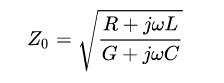
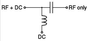
How would you use this if you are not given the R and the G? You could guess L and C. I know how Bias-Tees work and that a typical schematic would look like image below.
 Any help would be greatly appreciated :)
How would you use this if you are not given the R and the G? You could guess L and C. I know how Bias-Tees work and that a typical schematic would look like image below.