bigrobotworx
- 2
- 0
Hello brilliant engineers.
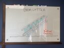
How to calculate the bending stress of a lattice boom crane design?
It’s clear how to calculate a single chord in a lattice box, at least as a cantilevered tube. However, when placed in a box lattice what is the proper approach?
I’m constructing this crane in conjunction with a big robot dragon. The “crane” is a telescoping tail that supports both riders and an aerial performer. The tail has two boom sections of 10 feet each, for an extended length of about 18 feet.
I’m attempting to determine the material specifications of the tube cords and lattice dimensions to operate the fully cantilevered working load, say 400 pounds, with a high safety factor (7x failure) to account for dynamic force and fabrication quality.
I believe the first 10 foot section can be calculated at 18 feet. Then the second section can be calculated at 8 feet independently.
Please help me understand the general approach. If there is a general rule between cords in a lattice configuration. And what formula to use, if it can be calculated manually.
I’m not an engineer. But can follow the math in https://www.physicsforums.com/threads/cantilever-beam-calculation.992690/
My eternal thanks and invitation to ride a big robot to any that can get me on the proper track!