Box Beam stress problem with welding

In summary: I'm not sure how feasible this would be, especially if the beam is to be used for anything other than a decoration3- this might be doable, but I'm not sure how practical it would be and what the implications would be, for example: would it be possible to weld the plates so that they could be easily removed if needed?4- this seems like the best option in the short term, though it may not be the most practical in the long term.
  • #1
Jackolantern
28
4
TL;DR Summary
half of aluminum beam is affected by weld heat, half isn't, will it hold up to the moment generated by the force?
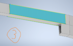
Hello All, I'm trying to figure out how to strengthen a box beam that's been welded to another box beam. In the photo on the left is 2 beams welded to each other, they are 2x1" Aluminum 6061-T6, with a 1/8" wall thickness. The yellow lines indicate the location of the weld. A force of 216 lbs is applied .723 meters away from the beam.

When aluminum 6061 T6 is welded, 5556 filler material can be used. The "Heat affected zone", or the area roughly 1 inch around a weld on aluminum will have greatly reduced mechanical properties, using filler material 5356, the yield strength of the HAZ is 15 ksi, compared to a yield strength of 35 ksi away from the HAZ. The filler metal has a yield strength close to >20ksi, so well focus on the weakest part of the weld- the HAZ.

If the maximum stress is calculated using sigma = My/Ixx

where M = 652.861 N-m, (it would be 694.995 N-m, but there is another force going downward that I forgot to include in the photo)
y = .0254 m (1")
Ixx = 1.380663 x 10^-7

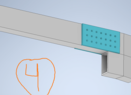
Thus, the max stress is approximately 120 Mpa, which is greater than our HAZ yield strength of 15 ksi, or 103.42 MPa. So I need to beef up the area of the Heat affected zone. In the picture to the right of the arrow, you can see that I have proposed welding another 2x1 piece of aluminum 6061, thereby increasing the effective height of the beam in the area and increasing the local strength of the HAZ to well beyond the maximum stress.

But there's a problem, by welding more aluminum under it, we get new HAZs as indicated by the red splotches, on the bottom of our top spar we have a HAZ with only 15 ksi yield strength, but it transitions back to regular 6061 with 35 ksi yield strength just 1" up. My question is, how can I calculate or be sure that this new section- half HAZ, half normal, will hold up to the approximate moment of 652.861 N-m as calculate earlier?

1677798061164.png
 
Engineering news on Phys.org
  • #2
  • #3
Lnewqban said:
Could you change the section to be welded from perpendicular to angled?
Could you weld plates onto top and bottom of beam?

Please, see:
https://en.wikipedia.org/wiki/Scarf_joint
I cannot change the section to be angled, as the two pieces are already at a 10 deg angle to each other, if I tried to do the scarf or interlocking method it wouldn't work due to the 10 deg bend, I think..

I could weld plates to the top and bottom, but I think this would just lead to the same issue of having that half HAZ, half normal section..
 
  • #4
Some ideas:
1) Make the top and bottom plates long enough that the stress in the HAZ will be low enough to be safe. Remember that the bending moment decreases as you get farther from the column.

2) Larger rectangular tube. If you have room to weld a 1 X 2 to a 1 X 2 tube, then there should be room for at least a 1 X 3 rectangular tube.

3) Make the added piece of 1 X 2 longer. Weld it directly to the vertical post, and make it long enough that the stress in the HAZ will be in the safe range.

4) Don't forget the safety factor.
 
  • #5
Jackolantern said:
I could weld plates to the top and bottom, but I think this would just lead to the same issue of having that half HAZ, half normal section..
But you would greatly increase the area moment of inertia to resist bending.
If heat is a problem, you could resort to mechanical fastening using rivets or bolts or even self-drilling metal screws.
Filling the hollow interior with a solid would prevent the walls to be deformed and less stress on the fasteners.

Please, see:
https://www.engineersedge.com/material_science/moment-inertia-gyration.htm#
 
  • #6
jrmichler said:
Some ideas:
1) Make the top and bottom plates long enough that the stress in the HAZ will be low enough to be safe. Remember that the bending moment decreases as you get farther from the column.

2) Larger rectangular tube. If you have room to weld a 1 X 2 to a 1 X 2 tube, then there should be room for at least a 1 X 3 rectangular tube.

3) Make the added piece of 1 X 2 longer. Weld it directly to the vertical post, and make it long enough that the stress in the HAZ will be in the safe range.

4) Don't forget the safety factor.
Thanks for your response J,

1- that sounds like a decent idea, though I'd like to avoid this method as the increase in strength doesn't seem very high, adding plates to the top and bottom would be like stacking rulers on top of each other then gluing them to together to resist a longitudinal load, and of course the HAZ would be affecting every inch of the plates if the plates are to be 1" in width.

2- I've hidden them, but there are pieces in the way just to the left of my proposed addition that would stop the use of 3x1" rectangular tubing.

3- I like the idea of extending it to the right up to the vertical post, there's nothing in the way there, but I cant extend it to the left unfortunately.
 
  • #7
Lnewqban said:
But you would greatly increase the area moment of inertia to resist bending.
If heat is a problem, you could resort to mechanical fastening using rivets or bolts or even self-drilling metal screws.
Filling the hollow interior with a solid would prevent the walls to be deformed and less stress on the fasteners.

Please, see:
https://www.engineersedge.com/material_science/moment-inertia-gyration.htm#
Hi L, mechanical fastening is a bit out of my purview, since there is a 10 deg bend at the weld, it would require that any plate or angle be bent to exactly 10 deg, bending aluminum plate isn't terrible complex but it does decrease its strength at the bend considerably, at least for 6061 I've found.

As for attaching plates to the top and bottom, I don't think it would increase the area moment of inertia much, unless I used really heavy thick plates. please see my reply to J above about the ruler anology.
 
  • #8
Jackolantern said:
bending aluminum plate isn't terrible complex but it does decrease its strength at the bend considerably, at least for 6061 I've found.
You could increase the radius of the bend, and then anneal the plates.
 
  • Like
Likes Jackolantern
  • #9
Annealing the plates back to a strength close to T6 would be difficult due to warping, and I'm no expert at it.

I've modeled some solutions to the problem, using ideas you suggested above, but instead of putting plates on the bottom, I think if I put them on the side it would work, maybe putting one on the bottom to resist cracking could work.

Solution 1: In photo 3 is two plates of 2x12”, 1/8” thick Al 6061 welded to the front and back of the top spar, by doing more welding along these plates, we will get more HAZs, but the idea is to push back (to the left of the beam) the un-reinforced section such that the lever arm is small enough that it can take the load. How much can I expect this method to increase the strength by?

Solution 2: In photo 4 is two plates riveted to the top spar, they are the same as solution 1’s plates, except they’re not as long since now we need only compensate for the original weld’s HAZ. How much can I expect this method to increase the strength by? I’m particularly worried about cracking at the bottom of the top spar, just below the riveted plate, would the riveted plate prevent cracking?
 

Attachments

  • Weld plate USE.png
    Weld plate USE.png
    23.3 KB · Views: 58
  • Riveted plate USE.png
    Riveted plate USE.png
    13.1 KB · Views: 61
  • #10
jrmichler said:
Some ideas:
1) Make the top and bottom plates long enough that the stress in the HAZ will be low enough to be safe. Remember that the bending moment decreases as you get farther from the column.

2) Larger rectangular tube. If you have room to weld a 1 X 2 to a 1 X 2 tube, then there should be room for at least a 1 X 3 rectangular tube.

3) Make the added piece of 1 X 2 longer. Weld it directly to the vertical post, and make it long enough that the stress in the HAZ will be in the safe range.

4) Don't forget the safety factor.
Jr, please see my new post to L
 
  • #11
Jackolantern said:
How much can I expect this method to increase the strength by?

You figure this for yourself by calculating the moment of inertia for various modifications of the box beam. Use search terms calculate moment inertia rectangular tube to find how to do that.
 
  • #12
jrmichler said:
You figure this for yourself by calculating the moment of inertia for various modifications of the box beam. Use search terms calculate moment inertia rectangular tube to find how to do that.
For the riveted plate I think I can find some material, but the welded plate I'm not so sure is so simple. Because it's not a rectangular tube anymore, there two weld points on each side and those are the only thing keeping the welded plate attached, the thickness of the added plate can't just be added to the overall thickness of the side walls, I think, I'm not sure, I've already done a search online and can't find much to shed light on it.
 
  • #13
If you add a plate, and weld it all around the perimeter, then it becomes part of the beam. You can weld plates to the sides, the top or bottom, or the top and bottom. The section I value is calculated as if the beam in the area of the plate is one solid part. If a plate is added to only the top or bottom, the I value and stress calculations are slightly more complicated. Do not add a side plate to only one side, the sides need to be balanced.

Riveted and bolted joints are more complicated to analyze. Since you have a highly stressed part, you should not use riveted or bolted reinforcements.
 
  • Like
Likes Jackolantern
  • #14
jrmichler said:
If you add a plate, and weld it all around the perimeter, then it becomes part of the beam. You can weld plates to the sides, the top or bottom, or the top and bottom. The section I value is calculated as if the beam in the area of the plate is one solid part. If a plate is added to only the top or bottom, the I value and stress calculations are slightly more complicated. Do not add a side plate to only one side, the sides need to be balanced.

Riveted and bolted joints are more complicated to analyze. Since you have a highly stressed part, you should not use riveted or bolted reinforcements.
"If you add a plate, and weld it all around the perimeter, then it becomes part of the beam. You can weld plates to the sides, the top or bottom, or the top and bottom. The section I value is calculated as if the beam in the area of the plate is one solid part."

-Can I ask how you know this, or some kind of source to validate this? I see you're a retired mechanical engineer so I feel like I should just take your word for it, but I'd like to learn more about it if I can.
 
  • #15
Now you are getting beyond what is practical for a forum post because I would need to write a book to fully answer your question. Fortunately, several people have written books that do this, and those books are far better than anything I could write.

Search Amazon for books using search terms mechanics of materials. The books by Hibbeler, and Beer and Johnston, are classics that are used to teach the subject. Get a copy and read it. It will answer your questions, plus the questions that come up after your first questions are answered. It will be a far more productive use of your time than trying to learn the subject by question and answer on a forum. A used copy of an earlier edition will meet your needs very nicely.

Jackolantern said:
I feel like I should just take your word for it, but I'd like to learn more about it if I can.
This is exactly the right approach. Keep it up.
 
  • Like
Likes Jackolantern and berkeman
  • #16
jrmichler said:
Now you are getting beyond what is practical for a forum post because I would need to write a book to fully answer your question. Fortunately, several people have written books that do this, and those books are far better than anything I could write.

Search Amazon for books using search terms mechanics of materials. The books by Hibbeler, and Beer and Johnston, are classics that are used to teach the subject. Get a copy and read it. It will answer your questions, plus the questions that come up after your first questions are answered. It will be a far more productive use of your time than trying to learn the subject by question and answer on a forum. A used copy of an earlier edition will meet your needs very nicely. This is exactly the right approach. Keep it up.
I see, well thanks for your help.
 
  • #17
jrmichler said:
Now you are getting beyond what is practical for a forum post because I would need to write a book to fully answer your question. Fortunately, several people have written books that do this, and those books are far better than anything I could write.

Search Amazon for books using search terms mechanics of materials. The books by Hibbeler, and Beer and Johnston, are classics that are used to teach the subject. Get a copy and read it. It will answer your questions, plus the questions that come up after your first questions are answered. It will be a far more productive use of your time than trying to learn the subject by question and answer on a forum. A used copy of an earlier edition will meet your needs very nicely. This is exactly the right approach. Keep it up.
Actually wait! I have one more question. What if you didn't weld directly around the perimeter, but instead welded a perimeter smaller than the total height and width of the second plate like in this photo? You wouldn't be able to then consider it as one piece then right?

1677951463419.png
 

1. What is a Box Beam stress problem with welding?

A Box Beam stress problem with welding refers to a common issue in which the welding process used to join two or more box beams together can cause stress concentrations in the beams, leading to potential failure or structural issues.

2. What causes stress problems in Box Beams during welding?

The stress problems in Box Beams during welding are caused by the uneven distribution of heat and pressure during the welding process. This can result in localized areas of high stress, which can weaken the structural integrity of the beams.

3. How can Box Beam stress problems be prevented during welding?

To prevent stress problems in Box Beams during welding, it is important to use proper welding techniques and ensure that the heat and pressure are evenly distributed. This can be achieved by using the correct welding equipment, following welding guidelines, and monitoring the temperature and pressure during the welding process.

4. What are the potential consequences of Box Beam stress problems with welding?

If Box Beam stress problems are not addressed, they can lead to structural failure, which can be dangerous and costly. The beams may also become more susceptible to corrosion and other forms of damage, further compromising their strength and stability.

5. Can Box Beam stress problems be repaired after welding?

In some cases, Box Beam stress problems can be repaired after welding. This typically involves using techniques such as heat treatment or post-weld stress relief to reduce the stress concentrations in the beams. However, prevention is always better than repair, so it is important to address any potential issues during the welding process to avoid costly repairs later on.

Similar threads

  • Mechanical Engineering
Replies
4
Views
6K
  • Mechanical Engineering
Replies
1
Views
1K
Replies
4
Views
2K
  • Engineering and Comp Sci Homework Help
Replies
11
Views
4K
  • Engineering and Comp Sci Homework Help
Replies
4
Views
2K
Back
Top