Calculating Effort Needed for Unevenly-Loaded Class 2 Lever

  • Thread starter Thread starter Jimbo86
  • Start date Start date
  • Tags Tags
    Class Lever
Join the discussion
Registration is free. Start your own thread to ask a follow-up.
8 replies · 4K views · last reply
Jimbo86
Messages
9
Reaction score
0
Hi,

I essentially have a class 2 lever, which holds an unevenly spread load. The lever itself (platform) is however an even weight throughout its length (except for the odd RSJ I've welded in for strength). This is an OLD machine, and hence we're going to build a bigger, stronger and higher capacity machine.

I've done a beam schematic and calculated the required effort to hold the platform with uneven weight in equilibrium. Which I think / hope is right. See below:
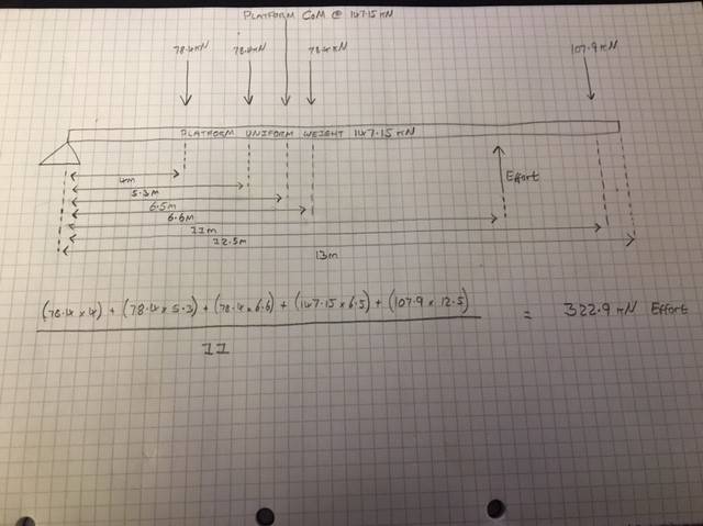
Hand-drawn free-body diagram of a class 2 lever with a fulcrum at the left end, showing platform, uniform and weight loads in kN at distances from the fulcrum, an effort arrow at 11 m, and a handwritten moment equation totalling 322.9 kN.


So 11 meters from the fulcrum will be the effort, which I've calculated needs to be 322.9kN for equilibrium.

Now below is the bit I'm slightly unsure of. I need to calculate the effort required to maintain equilibrium at different angles of the lift. And I presume as the angle of the lever increases the required effort reduces as the centre of gravity is essentially being shifted closer to the fulcrum? See below.
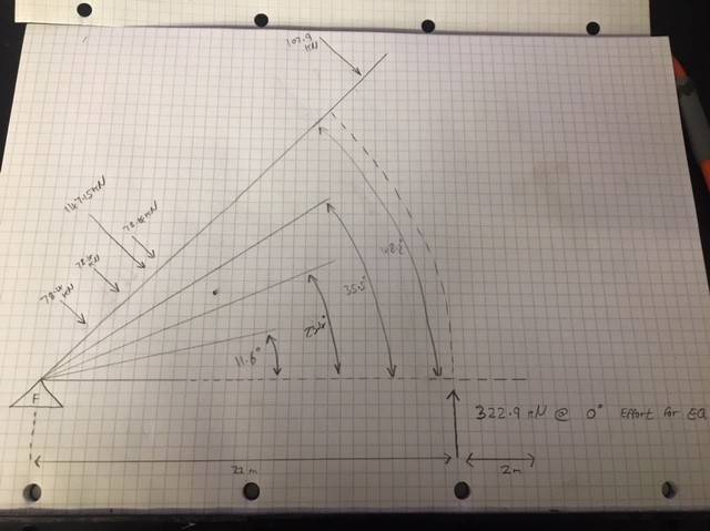
Hand-drawn side-view diagram of a lever with pivot F at the left, showing applied loads at 78.5 kN, 118.5 kN and 109.9 kN along the arm, an effort of 322.9 kN at 0 degrees, and dimensions of 21 m and 2 m.


What would be the best method used to calculate this?

Thanks,
Jim
 
Attachments
  • Hand-drawn free-body diagram of a class 2 lever with a fulcrum at the left end, showing platform, uniform and weight loads in kN at distances from the fulcrum, an effort arrow at 11 m, and a handwritten moment equation totalling 322.9 kN.
    1.jpg
    34.2 KB · Views: 1,342
  • Hand-drawn side-view diagram of a lever with pivot F at the left, showing applied loads at 78.5 kN, 118.5 kN and 109.9 kN along the arm, an effort of 322.9 kN at 0 degrees, and dimensions of 21 m and 2 m.
    2.jpg
    33.2 KB · Views: 1,229
Last edited by a moderator:
Physics news on Phys.org
I believe you have misstated in your post text that the length to the effort point is 11 meters; when, your diagram indicates that length is 22 meters. Which value is correct?
 
11 meters is correct. Sorry that’s my hand writing.
 
Do the load forces remain perpendicular to the platform when the angle increases ? (you designate them 'weights' and weights usually do maintain their direction)
 
Thanks for the reply.

The movable weight (I think that's right - pull of gravity on an object) is simply resting on the platform and stopped from moving by a beam near to the fulcrum. This beam is perpendicular to the platform at all times.

With regards to the load forces, as the platform rises I would assume that these forces are not perpendicular to the platform as they are when the platform is at 0 degrees (my second diagram force direction could be wrong). Reason being as the platform angle increases, gravity is pulling the load down towards the fulcrum. My thinking is that with platform angle increase the center of gravity of the weight is shifting closer to the fulcrum in a horizontal plane. So the higher the angle, the less effort is required to lift.

Only comparison I can think of is a wheelbarrow full of stone with a lid on it. The initial lift from flat is tough, but as the angle gets higher it becomes easier until it reaches over-center.

Hope this makes sense.

Thanks again
 
Well, since the problem is only partially defined, here is a partial answer.
IF the "Effort" stays perpendicular to the beam, then the force varies as the Cosine of the elevation angle.

If "Effort" does not stay perpendicular to the beam, you will have to account for the angle between "Effort" and the beam.
I'll leave that aspect to the other folks here!

Cheers,
Tom
 
Calculating the loading of lever beam:

(78.4*4)+(78.4*5.3)+(78.4*6.6)+(147.15*6.5)+(107.9*12.5) = 3551.785

Lets, just assume the effort is perpendicular to the load, with the platform @ 48.2 degrees:

(3551.785 * cos(48.2)) / 11 = 215kN effort required as opposed to 322.9kN @ 0 degrees.

In reality the effort would not be perpendicular:

Dimensioned sketch of a lever beam pivoting at its lower left end, inclined at 48.20 degrees to a horizontal base, with the beam length labelled 13000 and an angled support line from its upper end down to the base, labelled 67.28 degrees, and horizontal dimensions 13000 and 11000.
((3551.785 * cos(48.2)) / sin(67.28)) / 11 = 233.3kN required to lift platform @ 48.2 degrees with an effort applied @ 67.28 degrees.

Am I on the right track?
 
Attachments
  • Dimensioned sketch of a lever beam pivoting at its lower left end, inclined at 48.20 degrees to a horizontal base, with the beam length labelled 13000 and an angled support line from its upper end down to the base, labelled 67.28 degrees, and horizontal dimensions 13000 and 11000.
    angles.png
    40.3 KB · Views: 1,150
I agree witht the calculation.
Do 'not' understand how the 10765 appears