Calculating inductance -- Mystery units?

Click For Summary
SUMMARY

This discussion centers on the calculation of inductance for a motor using torque and angular speed, as outlined in a peer-reviewed journal paper. The participant attempts to replicate a figure from the paper, which presents inductance values derived from the equation La_10 = 1 / I_am * sqrt((V_om/N_a)^2 - Flux_PM.^2). The results yield imaginary inductance values, prompting confusion regarding the validity of the published results. The issue is attributed to the subtraction within the square root, indicating a potential error in the input parameters or their dependencies.

PREREQUISITES
  • Understanding of inductance calculations in electrical engineering
  • Familiarity with MATLAB or similar programming environments for plotting
  • Knowledge of torque and angular speed relationships in motor dynamics
  • Basic grasp of complex numbers and their implications in engineering calculations
NEXT STEPS
  • Review the principles of inductance calculations in electric motors
  • Learn MATLAB plotting techniques for visualizing engineering data
  • Investigate the implications of complex numbers in electrical engineering
  • Examine peer-reviewed papers on motor inductance for validation methods
USEFUL FOR

Electrical engineers, researchers in motor dynamics, and students studying electrical engineering concepts will benefit from this discussion, particularly those focused on inductance calculations and their practical applications.

Jamie1234
Messages
3
Reaction score
0
TL;DR
Corroborating the output of a trivial equation
Hello.
I would like to replicate the plot (a figure) provided in an example. The example is presented in a journal paper and shows the calculation for the inductance of a motor with known torque and angular speed.
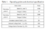
Below is the figure, and the table of parameters provided in the paper

1729664363257.png

1729664542237.png

Border 2 in the above figure is given by equation 10, below:
1729672998679.png

Calculating the inductance for the values of magnetic flux 0.24:0.05:0.260 as shown in the Figure, we obtain the values:
La_10 = 0.0000 + 0.0115i, 0.0000 + 0.0118i, 0.0000 + 0.0120i, 0.0000 + 0.0123i and 0.0000 + 0.0126i
Am I going mad?? :/ .

Code snippet:
N_a = 1500 % Speed [RPM]
Ta = 10 % Torque [Nm]
I_am = 20 % Armature current limit [A]
V_om = 100 % induced voltage limit [V]
V_lim = 160 % Voltage limit of inverter [V]
Flux_PM = [0.240:0.005:0.260]
La_10 = 1 / I_am * sqrt((V_om/N_a)^2 - Flux_PM.^2)
plot(Flux_PM, La)
 

Attachments

  • 1729664414363.png
    1729664414363.png
    16.7 KB · Views: 66
  • 1729664441274.png
    1729664441274.png
    16.7 KB · Views: 61
Engineering news on Phys.org
Welcome to PF.
Jamie1234 said:
Am I going mad?? :/ .
You have imaginary inductance values, so it may drive you mad.

I suspect the subtraction within the square root is doing that to you. You will need to check the absolute values of those variables before subtraction, one or both of them would appear to be wrong. Is one dependent on the other, and you are not evaluating that deeper dependency ?
 
Hi Bluncore. Thanks for your reply. Yes, mad as a hatter.

Yes, it's the subtraction in the square root as you mention. What gives me pause / confuses me; the paper was peer reviewed and published, the figure was constructed, and the results validated (in the paper). So it must be I that is mad..?

However; looking at the figure and table.
If we take a value on the x axis (flux linkage), say.. psi_a = 0.240, and from the table (and equation) we have, omega_base = Na = 1500 [RPM], and v_om = 100 [V], we obtain:
sqrt( ( v_om / omega_base)^2 - 0.240^2) = sqrt( (100 / 1500)^2 - 0.240^2) = sqrt( 0.0044 - 0.0576).

And yet, in the figure, for psi_a = 0.240 we have a value for the inductance of ~ 10.5 e-3 (shown in the figure to be the first point of boundary 2).

So who's crazy? and how has this magical value been obtained I wonder.
 
Last edited by a moderator:
Most likely this can only be answered by an "old timer". I am making measurements on an uA709 op amp (metal can). I would like to calculate the frequency rolloff curves (I can measure them). I assume the compensation is via the miller effect. To do the calculations I would need to know the gain of the transistors and the effective resistance seen at the compensation terminals, not including the values I put there. Anyone know those values?

Similar threads

Replies
4
Views
3K
Replies
1
Views
3K
  • · Replies 1 ·
Replies
1
Views
2K
Replies
4
Views
2K
  • · Replies 4 ·
Replies
4
Views
3K
  • · Replies 7 ·
Replies
7
Views
3K
  • · Replies 6 ·
Replies
6
Views
2K
  • · Replies 9 ·
Replies
9
Views
2K
  • · Replies 22 ·
Replies
22
Views
3K
  • · Replies 4 ·
Replies
4
Views
4K