Calculating of currents in a circuit

  • Thread starter Thread starter Antoha1
  • Start date Start date
AI Thread Summary
The discussion focuses on applying Kirchhoff's laws to analyze a circuit with two contours involving three batteries and a resistor. The first contour equation relates the voltages and currents in a counterclockwise direction, while the second contour incorporates a different path through the circuit. Participants confirm that the equations appear correct and suggest testing them with a simple case, such as identical batteries in parallel, to verify consistency. They emphasize the importance of using different loops to cross-check results, ensuring that the final answers align regardless of the chosen path. Proper application of Kirchhoff's laws is crucial for accurate calculations in circuit analysis.
Antoha1
Messages
15
Reaction score
2
Homework Statement
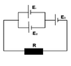
Three e. sources are connected as shown in the diagram.
What is the current flowing through the conductor and the sources when
it is known that E1=1.3 V, E2=1.5 V, E3=2V, r1=r2=r3=0.2 Ω, (##r##)
R=0.55 Ω.
Relevant Equations
Kirchhoff's 1st and 2nd laws;
##V=IR##
I am marking the current flowing through the conductor the same as currect flowing through the E3. (I3)
I am thinking of using Kirchhoff's laws in two contours. 1st contour would be the small one (E1 and E2) counter clock wise. 2nd contour would go through E3,E2,R (wouldn't go through E1).

For 1st contour (CCW):
##E_{1}-E_{2}=r(I_{1}-I_{2})##
2nd contour (CCW):
##E_{3}+E_{2}=I_{3}(r+R)+I_{2}r##
And Kirchhoff's 1st law for left node:
##I_{3}=I_{1}+I_{2}##

Now, that I have system of equations, I can calculate for everyone of them. (only if I applied Kirchhoff's laws correctly, of which I am not sure)
My question is: Did I apply the laws correctly and are these equations OK?
 

Attachments

  • Ekrano kopija 2025-04-25 225527.png
    Ekrano kopija 2025-04-25 225527.png
    1.2 KB · Views: 23
Physics news on Phys.org
It looks OK. You can also try them for some simple case. Like what happens if the two batteries in parallel are identical? Do you get the right result from your equations for this particular case?
 
It helps to have a diagram with the currents and their (assumed) directions marked.

You can check your work by solving with different loops. I would have chosen:
cell-1 to R to cell-3 back to cell-1 and
cell-2 to R to cell-3 back to cell-2.

You should, of course, get the same final answer whichever loops you use.
 
Kindly see the attached pdf. My attempt to solve it, is in it. I'm wondering if my solution is right. My idea is this: At any point of time, the ball may be assumed to be at an incline which is at an angle of θ(kindly see both the pics in the pdf file). The value of θ will continuously change and so will the value of friction. I'm not able to figure out, why my solution is wrong, if it is wrong .
Thread 'Voltmeter readings for this circuit with switches'
TL;DR Summary: I would like to know the voltmeter readings on the two resistors separately in the picture in the following cases , When one of the keys is closed When both of them are opened (Knowing that the battery has negligible internal resistance) My thoughts for the first case , one of them must be 12 volt while the other is 0 The second case we'll I think both voltmeter readings should be 12 volt since they are both parallel to the battery and they involve the key within what the...
Thread 'Trying to understand the logic behind adding vectors with an angle between them'
My initial calculation was to subtract V1 from V2 to show that from the perspective of the second aircraft the first one is -300km/h. So i checked with ChatGPT and it said I cant just subtract them because I have an angle between them. So I dont understand the reasoning of it. Like why should a velocity be dependent on an angle? I was thinking about how it would look like if the planes where parallel to each other, and then how it look like if one is turning away and I dont see it. Since...
Back
Top