radioglava
- 1
- 1
- Homework Statement
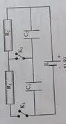
- Figure 89 is schematically represented by a circuit whose elements are: E = 60 V, R1= 3R2, C1 = 2C2. The internal resistance of the source is negligible. Determine the voltage on the capacitors in the following cases: a) switches K1, and K2 are closed, b) switch K2 open, a K1, closed, c) switch K2 closed, a K1 open.
- Relevant Equations
- I=U/R
U=C×Q
We had this for homework, my friends and I were able to solve the problems labeled with a) and b), but we got stuck at c).
From what we understood there is no voltage in resistor R1 because switch K1 is open. Resistor R1 is parallel to capacitor C1 so there is no voltage in capacitor C1, either. Our question is where does the current go if it can't go through C1? We know that the current must always return to the cell.
However, our textbook says that the voltage across capacitor 2 (C2) is equal to zero, and that the voltage across the first capacitor (C1) is equal to the emf.
From what we understood there is no voltage in resistor R1 because switch K1 is open. Resistor R1 is parallel to capacitor C1 so there is no voltage in capacitor C1, either. Our question is where does the current go if it can't go through C1? We know that the current must always return to the cell.
However, our textbook says that the voltage across capacitor 2 (C2) is equal to zero, and that the voltage across the first capacitor (C1) is equal to the emf.
Attachments