jackalsniper
- 10
- 0
the question goes like this:

the first part asks to utilize simulink to obtain the graph pattern:
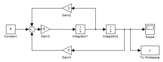
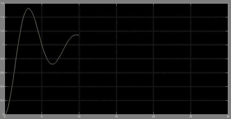
the second part requires us to make use of laplace transform and inverse laplace transform to solve the initial value problem:
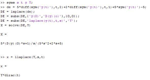
the third part asks us to compare both the results and comment, but how do i compare them
i'm not sure if the images could display or not, sorry
let me know if the images don't display, thanks
the first part asks to utilize simulink to obtain the graph pattern:
the second part requires us to make use of laplace transform and inverse laplace transform to solve the initial value problem:
the third part asks us to compare both the results and comment, but how do i compare them
i'm not sure if the images could display or not, sorry
let me know if the images don't display, thanks
Last edited: