Fan-motor system resonance problem

AI Thread Summary
The fan-motor system experiences resonance at a control frequency of 36.2 Hz, corresponding to an impeller frequency of 18.1 Hz, which falls within its operational range of 30 to 40 Hz. Despite attempts to mitigate the resonance through shaft realignment, impeller replacement, and enhanced vibration dampening, the issue persists. The discussion highlights the importance of identifying the source of vibration, whether mechanical or pneumatic, and suggests using frequency analysis tools to diagnose the problem. There is speculation that the fan may be operating in a surge zone, affecting performance during resonance. Further investigation into airflow, static pressure, and fan curve data is necessary to determine the root cause of the resonance issue.
ArnoVonck
Messages
18
Reaction score
4
TL;DR Summary
A fan-motor system goes into resonance at 36,2 Hz. It's not an electrical issue. I think it's mechanical but a lote of 'solutions' proved to be ineffective.
Hello everyone,

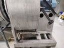
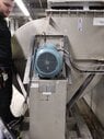
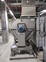
I am a student doing an internship at IMEC, Belgium. I am studying a fan driven by a motor. This fan-motor system goes into resonance at a control frequency of 36.2 Hz. This corresponds to 18.1 Hz impeller frequency. The operating range of this fan is 30 to 40 Hz, so we can't just skip these frequencies. We have tried several things to get the system to stop resonating, but nothing seems to work. We have already realigned the shaft with the motor. (Motor and fan are directly coupled) We've also tried replacing the impeller with a new one, replacing the bearings, adding reinforcements to increase rigidity, and we've even put better vibration dampers under the system. I don't know what else I can do, so I'm asking for your help. Feel free to comment with your findings. Thanks in advance!

Arno Vonck
 
Engineering news on Phys.org
Welcome to PF. :smile:

Do you have access to a strobe light? It might be instructive to slew around near resonance and at resonance to see what-all is moving. That may help to give you some clues as to how to decrease the movement and resonance(s).
 
  • Like
  • Informative
Likes ArnoVonck, russ_watters, DaveE and 1 other person
Welcome, @ArnoVonck !

How have you determined the 18.1 Hz impeller frequency?
Should not this value be equal to the control frequency if motor and fan are directly linked?

How would you describe the resonance of the system?
What is the direction of the greatest oscillation?

Could it be that the fan is working on an oscilating or surging zone of its operational curve?
Does its perfomance vary while the resonance lasts?

Could you post a picture of the system?
 
  • Like
Likes ArnoVonck and russ_watters
Does the fan operate in a duct? How long is the duct?

What type of fan or blower? How many blades?
 
  • Like
Likes ArnoVonck and Rive
What if any effect does the fan's load have on the resonance? Suppose you block the inlet to dramatically reduce the airflow, ideally to zero, what happens. This may allow you to separate fan/airfoil design issues from mechanical issues.

You can often gain some insight into the salient components of the resonance by making alterations, like adding mass and such, and seeing if you can alter the resonant frequency.
 
If the drive frequency is 36.2 Hz, and the resonance is at 18.1 Hz, then that implies (and you need to confirm) that the fan is spinning at 18.1 X 60 = 1086 RPM. We need to know what is vibrating:

Is the fan running 1086 RPM at 36.2 Hz drive frequency?
Is it a pneumatic vibration (air vibrating in the duct)?
Is it a mechanical vibration (fan/motor assembly shaking)?
Is the vibration frequency 18.1 Hz, or is something shaking when the fan is running 1086 RPM?
Or is the vibration frequency 18.1 X the number of blades in the fan?
Or is the vibration frequency a different frequency?

There are cell phone apps that display frequencies in the audible range. The screenshot below is from one such app. It shows the frequencies from a noisy fan on my heat recovery ventilator. The 120 Hz frequency is probably magnetostrictive vibration in the blower motor, and the closely spaced frequencies around 1000 Hz are from the noisy bearing.
Noisy blower.jpg


A pair of similar screenshots from you would be very helpful. One at the bad speed, the other at a good speed.
 
  • Like
Likes ArnoVonck, Rive, DaveE and 1 other person
jrmichler said:
There are cell phone apps that display frequencies in the audible range.
Cool app! What's it called?
 
Lnewqban said:
Could it be that the fan is working on an oscilating or surging zone of its operational curve?
Does its perfomance vary while the resonance lasts?
That's my guess. If the fan is balanced there can't be any vibration/mechanical resonance, so it would have to be a surge problem. We'd need to see the fan curve and get a measurement of airflow and pressure to verify where it is operating on the curve.

In general, high pressure + low flow = surge.
 
berkeman said:
Cool app! What's it called?
Spectral Pro Analyzer for Android. In general it'd be a search for "frequency spectrum analyzer".
 
  • #10
The app is Spectroid.
Spectroid.jpg

One of the reviews (boldface by me):
Frankly, this app helps restore my faith in humanity. Simple. Clean. Elegant, useful. No ads, no popups. I know the author points out he can't calibrate but just for fun, pull up an online tone generator on an adjacent computer and try comparing the results. I'm using this to debug some objectionable noise from some industrial fans. What a nice find. Thanks. Like a few others, I'd love the ability to record an audio clip along with the spectrum analysis. Not a big deal though. Bravo
 
  • Like
  • Informative
Likes Rive, russ_watters and berkeman
  • #12
berkeman said:
Welcome to PF. :smile:

Do you have access to a strobe light? It might be instructive to slew around near resonance and at resonance to see what-all is moving. That may help to give you some clues as to how to decrease the movement and resonance(s).
I do not have access to a strobe light, we did do motion amplification measurements and other standard vibration measurements on the fan and motor though. These told us that the 'snail house' and motor base were moving into eachother. I actually have some great videos of this but I just noticed you can't attach video's to a post. I added a picture of the motor-fan system though.
 

Attachments

  • WhatsApp Image 2023-03-13 at 15.13.17 (2).jpeg
    WhatsApp Image 2023-03-13 at 15.13.17 (2).jpeg
    44.7 KB · Views: 116
  • WhatsApp Image 2023-03-13 at 15.13.17 (6).jpeg
    WhatsApp Image 2023-03-13 at 15.13.17 (6).jpeg
    36.2 KB · Views: 138
  • WhatsApp Image 2023-03-13 at 15.13.17.jpeg
    WhatsApp Image 2023-03-13 at 15.13.17.jpeg
    39.6 KB · Views: 139
  • #13
Lnewqban said:
Welcome, @ArnoVonck !

How have you determined the 18.1 Hz impeller frequency?
Should not this value be equal to the control frequency if motor and fan are directly linked?

How would you describe the resonance of the system?
What is the direction of the greatest oscillation?

Could it be that the fan is working on an oscilating or surging zone of its operational curve?
Does its perfomance vary while the resonance lasts?

Could you post a picture of the system?
Thank you Lnewqban.

I may have phrased it wrongly. A frequency of 40 Hz coming out of the VFD, corresponds with a mechanical rotation of 20 Hz. Well, I would like to show you guys the videos we made, is there any way to upload them here? This way you could all see the way the system behaves when vibrating. I don't know about the oscilating/surging zone, I will look into this! I don't think the performance varies while the resonance lasts.
 

Attachments

  • WhatsApp Image 2023-03-13 at 15.13.17.jpeg
    WhatsApp Image 2023-03-13 at 15.13.17.jpeg
    39.6 KB · Views: 142
  • WhatsApp Image 2023-03-13 at 15.13.17 (6).jpeg
    WhatsApp Image 2023-03-13 at 15.13.17 (6).jpeg
    36.2 KB · Views: 135
  • WhatsApp Image 2023-03-13 at 15.13.17 (2).jpeg
    WhatsApp Image 2023-03-13 at 15.13.17 (2).jpeg
    44.7 KB · Views: 126
  • #14
jrmichler said:
If the drive frequency is 36.2 Hz, and the resonance is at 18.1 Hz, then that implies (and you need to confirm) that the fan is spinning at 18.1 X 60 = 1086 RPM. We need to know what is vibrating:

Is the fan running 1086 RPM at 36.2 Hz drive frequency?
Is it a pneumatic vibration (air vibrating in the duct)?
Is it a mechanical vibration (fan/motor assembly shaking)?
Is the vibration frequency 18.1 Hz, or is something shaking when the fan is running 1086 RPM?
Or is the vibration frequency 18.1 X the number of blades in the fan?
Or is the vibration frequency a different frequency?

There are cell phone apps that display frequencies in the audible range. The screenshot below is from one such app. It shows the frequencies from a noisy fan on my heat recovery ventilator. The 120 Hz frequency is probably magnetostrictive vibration in the blower motor, and the closely spaced frequencies around 1000 Hz are from the noisy bearing.
View attachment 323917

A pair of similar screenshots from you would be very helpful. One at the bad speed, the other at a good speed.
Thank you, jrmichler!
Exactly, the fan spins at 1086 RPM.
- Yes, 1086 RPM at 36,2 Hz drive frequency.
- I don't think these are pneumatic vibrations. I think it's a mechanical issue. Motor and fan are as it were, moving 'into' eachother whilst vibrating.
- The main resonance frequency of the system is 18,1 Hz (36,2 VFD frequency), when the fan rotates at this frequency, the system starts to heavily vibrate. This isn't the only frequency on which the system vibrates though. When I get the results of our new measurements I'll share them with you guys.
 
  • #15
ArnoVonck said:
I may have phrased it wrongly. A frequency of 40 Hz coming out of the VFD, corresponds with a mechanical rotation of 20 Hz.
You're expressing that in a weird way, but:
20Hz * 60 s/m = 1200 rpm. Fine.
Well, I would like to show you guys the videos we made, is there any way to upload them here? This way you could all see the way the system behaves when vibrating. I don't know about the oscilating/surging zone, I will look into this! I don't think the performance varies while the resonance lasts.
I don't think so. Can you upload to YouTube or another sharing service?

A thrust vibration sounds like a symptom of surge to me, but I'm less familiar with vibration analysis and more familiar with airflow analysis: do you have the airflow, static pressure and fan curve?
 
  • #16
Baluncore said:
Does the fan operate in a duct? How long is the duct?

What type of fan or blower? How many blades?
It pushes media into a duct yes. The media is NaOH. We've actually separated the duct once and let it rotate freely. The system still goes into resonance. It's a centrifugal fan (radial) with backward curve impeller type. I actually don't know the amount of blades and I can't find it in the documents available to me.
 
  • #17
russ_watters said:
You're expressing that in a weird way, but:
20Hz * 60 s/m = 1200 rpm. Fine.

I don't think so. Can you upload to YouTube or another sharing service?

A thrust vibration sounds like a symptom of surge to me, but I'm less familiar with vibration analysis and more familiar with airflow analysis: do you have the airflow, static pressure and fan curve?
I'm not a native English speaker, don't mind my weird expressions. I uploaded the video's to youtube, but they are confidential to IMEC, so you can only access them through these links.
The nominal flow of this fan is 20 000 m³/h. I'm looking for the static pressure and fan curve, I'll upload it here when I find it.
Video 1:
Video 2:
 
  • #18
ArnoVonck said:
The nominal flow of this fan is 20 000 m³/h. I'm looking for the static pressure...
This doesn't mean anything: they need to be measured (unless the engineer made a selection mistake, which is unlikely to be the problem here).

How is the fan/system controlled? Airflow, static pressure or none?

[Edit] A bit of googling tells me axial vibration isn't common and isn't likely to be airflow related. It could be shaft misalignment or thrust bearing failure.
 
Last edited:
  • Like
Likes ArnoVonck and Lnewqban
  • #19
russ_watters said:
This doesn't mean anything: they need to be measured (unless the engineer made a selection mistake, which is unlikely to be the problem here).

How is the fan/system controlled? Airflow, static pressure or none?
What do you mean by controlled? We want to control the flow of NaOH going through.
 
  • #20
ArnoVonck said:
What do you mean by controlled?
I mean does the fan run at constant speed or is there a control system that changes the speed according to a measurement?
We want to control the flow of NaOH going through.
Could be a language barrier here, but surely it is mostly plain air flowing through it? You're "controlling" (preventing) human exposure to naoh?
 
  • #21
russ_watters said:
I mean does the fan run at constant speed or is there a control system that changes the speed according to a measurement?
Yes the speed is being controlled by a VFD. The VFD responds to the PIC as you can see in the document I added (the problem fan is the one called 813-F11)
russ_watters said:
Could be a language barrier here, but surely it is mostly plain air flowing through it? You're "controlling" (preventing) human exposure to naoh?
No, there's actually NaOH flowing through. Not air.
 

Attachments

  • #22
ArnoVonck said:
No, there's actually NaOH flowing through. Not air.
I can see the confusion here. The NaOH flowing through is dissolved in water.
 
  • #23
russ_watters said:
We'd need to see the fan curve and get a measurement of airflow and pressure to verify where it is operating on the curve.
Does the document attached suffice?
 

Attachments

  • #24
A motor bearing defect could be the problem. VFD-driven motors can (and do) develop bearing issues as a result of induced currents which (ultimately) damage the bearings/races (like a 'washboard' dirt road). An inspection of the bearings (go ahead and replace them while you're there) or temporary installation of a 'soft' motor coupling may be useful troubleshooting steps.
 
  • Like
Likes russ_watters and ArnoVonck
  • #25
Dullard said:
A motor bearing defect could be the problem. VFD-driven motors can (and do) develop bearing issues as a result of induced currents which (ultimately) damage the bearings/races (like a 'washboard' dirt road). An inspection of the bearings (go ahead and replace them while you're there) or temporary installation of a 'soft' motor coupling may be useful troubleshooting steps.
We first replaced the bearings with non-conductive bearings. Then we replaced the entirety of the motor. So the motor/bearings aren't the problem.
 
  • #26
Has the impeller been replaced?
If so, have both resonated at the same rotational speed?
Have both been balanced, both statically and dynamically?
Same shaft for both impellers?

Could you explain a little more about the fluid being transferred?
Is it a gas carrying no solids or mist?
If not, could some deposits being build on the vanes of the impeller?

Thank you for the pictures.
Could you show some pictures of the coupling and bearings?
 
  • #27
It appears that the blower is supported by its side plate, and that the vibration is flexing that side plate. If that's correct, the vibration will eventually cause the side plate to crack, with the cracks starting at the two points circled because those two areas are where the most side plate bending is happening.
Blower1.jpg

Run the speed up and down through the bad speed while closely watching those two areas. It looks safe to touch there, so holding your hand there will tell you a lot. If the motor base is relatively still, the side plate close to the steel angles is still, and the side plate outside the circles is vibrating, then the problem source is almost certainly located.

Let us know what you find because that will determine the next step.

Also, balancing the impeller cannot hurt, and will almost certainly help. But it will very likely not cure the problem completely.
 
  • #28
Lnewqban said:
Has the impeller been replaced?
If so, have both resonated at the same rotational speed?
Have both been balanced, both statically and dynamically?
Same shaft for both impellers?

Could you explain a little more about the fluid being transferred?
Is it a gas carrying no solids or mist?
If not, could some deposits being build on the vanes of the impeller?

Thank you for the pictures.
Could you show some pictures of the coupling and bearings?
Yes the impeller has been replaced with a completely new one. Both have been balanced, statically and dynamically. I'm kind of rethinking the weights on the impeller to balance it out though. I might take them off and do a run-up again.

The fluid being transferred is NaOH dissolved in water. Its purpose: to bring the pH-value of water with low pH-value up. There is most certainly some deposits on the vanes. But the problem was already there before the build-up of these. I'm not on the company right now. But it's not that easy to show pictures of bearings and couplings since the place has to go in shutdown to turn the fan off. (It runs on 30 Hz now)

I'm planning a moment to do changes to the unit and keeping all of you guys' thoughts in mind to do them during this moment. I'll keep you guys up to date for sure though!
 
  • #29
jrmichler said:
It appears that the blower is supported by its side plate, and that the vibration is flexing that side plate. If that's correct, the vibration will eventually cause the side plate to crack, with the cracks starting at the two points circled because those two areas are where the most side plate bending is happening.
View attachment 323983
Run the speed up and down through the bad speed while closely watching those two areas. It looks safe to touch there, so holding your hand there will tell you a lot. If the motor base is relatively still, the side plate close to the steel angles is still, and the side plate outside the circles is vibrating, then the problem source is almost certainly located.

Let us know what you find because that will determine the next step.

Also, balancing the impeller cannot hurt, and will almost certainly help. But it will very likely not cure the problem completely.
We've actually done a new vibration measurement on the entire motor-fan unit, on many different measurement points etc.. I'm still awaiting these results but these should be in by monday. Btw: The diagonal bars you see from motor base to snail house, together with the vertical bars from motor base to snail house weren't always there. We put them there on advice of RUCON (the manufacturer of this fan) because they thought it might help. It didn't..
 
  • #30
ArnoVonck said:
This fan-motor system goes into resonance at a control frequency of 36.2 Hz.
The topic is totally out of my expertise, so it's just a (possibly very stupid) thought, but: what if you have some kind of 'musical' resonance there?

Any connected straight ducts or whatever there with matching length to the half- or full wavelength? (assuming the wavelength in the delivered 'air' based on 'real air')
 
  • #31
ArnoVonck said:
Yes the impeller has been replaced with a completely new one. Both have been balanced, statically and dynamically.
.....
There is most certainly some deposits on the vanes. But the problem was already there before the build-up of these.

Dynamic balancing is the key in this case, but it should be done as an assembly (all the rotating masses), including shaft and key.
If not possible, testing the dynamic balance of the shaft alone could eliminate the possibility of a bent shaft (which I suspect).

Besides any fluid pulsing cause (if any), the resonance problem must have its root in masses that rotate out of balance, even if in a very small magnitude.
If that lack of balance can't be located and measured and corrected, modifying things to increase the natural frequency of the vibrating system is the next step.
Evidently, those added angles did not do much for that.

What is the meaning of your following statement?
I'm kind of rethinking the weights on the impeller to balance it out though.
... it's not that easy to show pictures of bearings and couplings since the place has to go in shutdown to turn the fan off. (It runs on 30 Hz now)
No problem, just trying to understand the arrangement of motor, coupling, shaft, air seal (if any) and bearings.
If not possible, pictures from different angles around the fan could help us.

It seems to be a cantilever impeller arrangement, which can make vibrations worse.
One of your pictures seem to show a solid bridge by-passing the isolation of duct-fan provided by the canvas connection.

Any luck with a video via YouTube?
 
  • #32
Lnewqban said:
Any luck with a video via YouTube?
I shared some links to these video's in a reply above
ArnoVonck said:
Video 1:
Video 2:
Here they are
 
  • #33
Lnewqban said:
What is the meaning of your following statement?
The fan has been balanced out by adding some weights to the impellers. This has been done when I wasn't on internship here yet. When I looked at the fan spinning without media through it, it seemed these weights were actually Off-balancing the impeller. I'm thinking about taking the weights off and then seeing how the system does when rotating.
 
  • #34
Be sure to mark which weight goes where. That will save you a LOT of time if things get worse without them! :eek:

Also was the original balancing a static balance or a dynamic balance in 3 dimensions?
i.e. the usual out-of-round or off-center mounting problem
versus
also balancing for wobble parallel to the spin axis. (important for centrifugal fans)
 
  • Like
Likes ArnoVonck, berkeman and Lnewqban
  • #35
Lnewqban said:
No problem, just trying to understand the arrangement of motor, coupling, shaft, air seal (if any) and bearings.
If not possible, pictures from different angles around the fan could help us.
I'm sorry for the late answer. I've been on a holiday. I've went and took some pictures of the entire unit to maybe get you a better idea.
 

Attachments

  • WhatsApp Image 2023-04-18 at 10.17.32 (1).jpeg
    WhatsApp Image 2023-04-18 at 10.17.32 (1).jpeg
    46.3 KB · Views: 128
  • WhatsApp Image 2023-04-18 at 10.17.32 (2).jpeg
    WhatsApp Image 2023-04-18 at 10.17.32 (2).jpeg
    48.8 KB · Views: 134
  • WhatsApp Image 2023-04-18 at 10.17.32 (3).jpeg
    WhatsApp Image 2023-04-18 at 10.17.32 (3).jpeg
    38.5 KB · Views: 110
  • WhatsApp Image 2023-04-18 at 10.17.32.jpeg
    WhatsApp Image 2023-04-18 at 10.17.32.jpeg
    40.8 KB · Views: 117
  • WhatsApp Image 2023-04-18 at 10.17.33 (2).jpeg
    WhatsApp Image 2023-04-18 at 10.17.33 (2).jpeg
    28.4 KB · Views: 124
  • WhatsApp Image 2023-04-18 at 10.17.33 (1).jpeg
    WhatsApp Image 2023-04-18 at 10.17.33 (1).jpeg
    38.1 KB · Views: 131
  • WhatsApp Image 2023-04-18 at 10.17.33 (3).jpeg
    WhatsApp Image 2023-04-18 at 10.17.33 (3).jpeg
    44.7 KB · Views: 123
  • WhatsApp Image 2023-04-18 at 10.17.33.jpeg
    WhatsApp Image 2023-04-18 at 10.17.33.jpeg
    42.6 KB · Views: 124
  • WhatsApp Image 2023-04-18 at 10.17.34 (1).jpeg
    WhatsApp Image 2023-04-18 at 10.17.34 (1).jpeg
    42.6 KB · Views: 112
  • WhatsApp Image 2023-04-18 at 10.17.34.jpeg
    WhatsApp Image 2023-04-18 at 10.17.34.jpeg
    60.1 KB · Views: 115
  • #36
When you run it a rated design rpm (1470 rpm), are you getting rated static pressure?

Are there other systems tied into the duct? I assume it's going to a scrubber?
 
  • Like
Likes russ_watters and ArnoVonck
  • #37
Based on Video #2 in Post #17, it appears that the blower housing has a mechanical vibration at 18.2 Hz. Mechanical vibrations are analyzed as spring - mass systems. The mass in this system is the blower housing, the spring is the side of the housing in the photos, and the motor base is fixed. That's why the request for the test in Post #27. Sometimes, your fingers are all the test equipment that you need. This might be one of those times, but you need to run the test to find out.

If so, the remedy is simple. Weld on a pair of stiffeners as shown by the heavy black lines in the image below.

Blower.jpg

You can leave the angled braces where they are, or make new ones that connect the same location on the base to the top of the stiffeners.

The theory is as follows: Natural frequency = ##\sqrt{\left( \frac K M \right)}##, where:
K = Stiffness
M = Mass
Since we want to increase natural frequency from 18 Hz to a value above the maximum operating speed of 30(?) Hz, it is necessary to increase the ratio of K to M by about a factor of 4. Reducing the vibrating mass that much is not practical, but it is practical to increase the stiffness. The stiffness of a thin plate is very low, and it is easy to increase that stiffness by a factor of several times by adding the stiffeners shown.
 
  • Like
Likes russ_watters, ArnoVonck and DaveE
  • #38
A thought: Those diagonal stiffeners ? Do they resonate ?? If so, can you add masses to 'quench' them ??
 
  • #39
jrmichler said:
That's why the request for the test in Post #27.
The 3rd of May we'll do another run-up test. I'll do as you said in Post #27
 
  • #40
erobz said:
When you run it a rated design rpm (1470 rpm), are you getting rated static pressure?

Are there other systems tied into the duct? I assume it's going to a scrubber?
No we don't get rated static pressure. Indeed, it's going to a scrubber.
 
  • #41
ArnoVonck said:
No we don't get rated static pressure. Indeed, it's going to a scrubber.
I'm assuming your s.p. was too high, which was why it is currently being run at 1086 rpm? Or is it the vibrations just passing through 1086 rpm on the way to 1470 rpm the issue?
 
Back
Top