Finding voltage across a resistor using Kirchhoff's laws

6 replies · 3K views · last reply
TomK
Messages
69
Reaction score
14
Homework Statement
Can't do circuit problems with 2+ cells consistently. It works for some questions and doesn't for others. I'm guessing this is because my mistakes in one question end up cancelling each other out. I don't get it.
Relevant Equations
https://www.ocr.org.uk/Images/536433-data-sheet.pdf
I wasn't taught how to do it at A-Level in-detail, because there are no questions that expect you to use them in a circuit problem. They only need you to know what the first and second laws are in words (i.e. conservation of charge and energy).

I tried looking it up on YT, but it's confusing. All I know is this:1) Choose a direction for current to flow (CW or ACW) - consistent for every loop.

2) Choose a p.d. direction (+ to -, or - to +) - consistent for every loop.

3) current into a junction = current out of same junction.

4) sum of potentials in a closed loop = 0. This doesn't make sense to me, but I use it anyway.

5) If p.d. and current direction are against each other, add emf and component potentials. If p.d. and current direction are in same direction, subtract component potentials from emf.I don't know what counts as a loop. Does it have to start and end at the same cell, or can a loop not involve a cell at all?

Whenever I have a loop that has a second cell in the way, I check if its p.d. direction opposes that of my starting cell. If it does, I subtract its potential from the emf of the starting cell.

I still can't do this question, though.
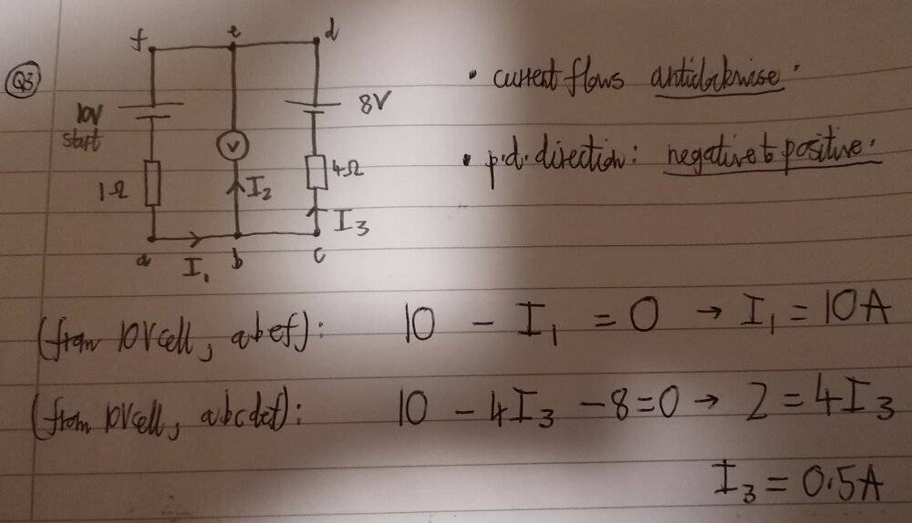
Handwritten circuit diagram labelled Q3 with nodes a to f: a 10V cell with 1 ohm resistor in one branch, a voltmeter between b and e, and an 8V cell with 4 ohm resistor in a second branch, with currents I1, I2 and I3 marked, followed by handwritten loop equations giving I1 = 10A and I3 = 0.5A.
Circuit schematic with a voltmeter between two branches: left branch has a cell of emf 10V in series with a 1.0 ohm resistor, right branch has a cell of emf 8.0V in series with a 4.0 ohm resistor. Handwritten question: What is reading on the voltmeter?


The answer is 9.6V, but I can't see why.
 
TomK said:
Homework Statement:: Can't do circuit problems with 2+ cells consistently. It works for some questions and doesn't for others. I'm guessing this is because my mistakes in one question end up cancelling each other out. I don't get it.
Relevant Equations:: https://www.ocr.org.uk/Images/536433-data-sheet.pdf

I wasn't taught how to do it at A-Level in-detail, because there are no questions that expect you to use them in a circuit problem. They only need you to know what the first and second laws are in words (i.e. conservation of charge and energy).

I tried looking it up on YT, but it's confusing. All I know is this:1) Choose a direction for current to flow (CW or ACW) - consistent for every loop.

2) Choose a p.d. direction (+ to -, or - to +) - consistent for every loop.

3) current into a junction = current out of same junction.

4) sum of potentials in a closed loop = 0. This doesn't make sense to me, but I use it anyway.

5) If p.d. and current direction are against each other, add emf and component potentials. If p.d. and current direction are in same direction, subtract component potentials from emf.I don't know what counts as a loop. Does it have to start and end at the same cell, or can a loop not involve a cell at all?

Whenever I have a loop that has a second cell in the way, I check if its p.d. direction opposes that of my starting cell. If it does, I subtract its potential from the emf of the starting cell.

I still can't do this question, though.
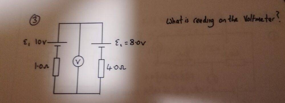
View attachment 270531View attachment 270532

The answer is 9.6V, but I can't see why.
You cannot assume there is a 10V drop across the 1Ω resistor. That's a voltmeter in the middle, so cannot be counted as completing a circuit, i.e. I2 is zero.
You can take that link out, leaving you with two resistors in series and two (opposing) emfs in series.
 
haruspex said:
You cannot assume there is a 10V drop across the 1Ω resistor. That's a voltmeter in the middle, so cannot be counted as completing a circuit, i.e. I2 is zero.
You can take that link out, leaving you with two resistors in series and two (opposing) emfs in series.

I thought that too, since we should assume the voltmeter is of infinite resistance. This is what I have written:

10 - I - 4I - 8 = 0
5I = 2
I = 0.4A

How do I calculate the potential difference now?
 
TomK said:
I thought that too, since we should assume the voltmeter is of infinite resistance. This is what I have written:

10 - I - 4I - 8 = 0
5I = 2
I = 0.4A

How do I calculate the potential difference now?
Calculate the voltage drop across one resistor.
 
haruspex said:
Calculate the voltage drop across one resistor.

The calculation works out now.

I wanted to ask: why does the p.d. on the 'left side' (with the 10V cell) have to be the same as the p.d. on the 'right side' (with the 8V cell)? I know the voltmeter is in-parallel with both sides. It's confusing for me to think about, because the voltmeter is sandwiched between what would be a series circuit.

In a circuit problem, will you ever have to write an equation for a loop with no cell? I asked before: does a loop have to start and end at a cell?

I was doing this other question involving Kirchhoff's Laws, but I must have made a mistake somewhere. Would you be able to help? The answer should be 2A.

Circuit schematic with an ammeter A, cells of 8.0V and 4.0V, and resistors of 1.0, 2.0, 2.0 and 4.0 ohms, with the question 'What is the reading on the ammeter?'
Handwritten Kirchhoff's laws working for circuit Q4: loop equations, substitution I3 = I1 - I2, and I2 = 2.5 A giving I1 = 9 A, marked 'should be 2A!'
 
TomK said:
why does the p.d. on the 'left side' (with the 10V cell) have to be the same as the p.d. on the 'right side'
Consider the four corners of the bounding rectangle. Voltage top left=voltage top right; voltage bottom left =voltage bottom right.
TomK said:
does a loop have to start and end at a cell?
Yes. It has to be a circuit, and it has to include something that will create a potential difference even when there is no current.
TomK said:
made a mistake somewhere
How come it is -I1 and -4I3 but +2I2 ?
 
haruspex said:
Consider the four corners of the bounding rectangle. Voltage top left=voltage top right; voltage bottom left =voltage bottom right.

Yes. It has to be a circuit, and it has to include something that will create a potential difference even when there is no current.

How come it is -I1 and -4I3 but +2I2 ?

I think the hardest part about this question is knowing when to add or subtract a potential.

From what I know, when current and p.d. direction are opposed in a loop, the components the current goes through will add potentials onto the emf of the starting cell. When current and p.d. direction are the same in a loop, component potentials will be subtracted from the cell emf.

In the loop I have labelled as 'abef', it gets confusing, because the negative terminal of the starting 8V cell goes to the negative terminal of a 4V cell that is in the way. I assumed this meant subtract 4V from the 8V in my equation. As for the 2 ohm resistor, it looked like current was traveling up. I think the second cell confused me into thinking the p.d. direction and current flow were opposed, when they were actually going the same way if you only consider the starting cell's p.d. direction.

I think the method should go like this. If the p.d. direction of the STARTING cell and the current flow are the same, then the component potential subtracts from the STARTING cell emf. The orientation of the second cell should only affect whether I add or subtract 4V from the starting 8V cell. It shouldn't factor into whether I subtract or add the resistor potential. Therefore, I should have subtracted the '2I2' in the equation, not added it.

Is what I'm saying right? I changed my equation, and it now gives me the answer of 2A which is correct. I hope I've figured the method out now. Thank you for your help.