kekpillangok
- 15
- 2
- Homework Statement
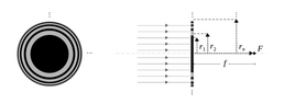
- Bob wants to focus a collimated monochromatic beam at a point F. Due to the small wavelength λ, he cannot use an ordinary converging lens to focus this radiation. As an alternative, he intends to use a diffraction grating made up of concentric rings round an absorbing (opaque) disc of radius r1. The concentric rings alternate between opaque/absorbing rings (the black ones in the images) and rings that let light through (the grey ones in the images).
Find an expression for the radii r_n (n > 1) of the concentric rings, which can be absorbing (when n is odd) or letting light through (when n is even), as a function of λ, r1, of the distance f from the centre of the rings to the point F, and of the integer index n, so that the rings will focus the beam at F.
- Relevant Equations
- d(a,b) = sqrt(a^2 + b^2)
delta_x = m * lambda
The first image shows the rings and the absorbing disc from the front; the second shows them from the side.
I am told that, to solve this problem, I have to imagine a light source located at ##r _{1 } ##. The light passing through the "open" rings (the ones that let light through, located at the even-numbered radii), then, should have a 180° phase difference relative to the light coming from this nonexistent source. I am to write, then, $$d _{n }-d _{1 }={\left( n -1 \right) }\cdot \frac{\lambda }{2 },\text{n even }$$,
where $$d _{n }=\sqrt{{r _{n }}^{2 }+{f }^{2 }} $$—the distance from each gap to the point ##f ##. This lets me find a general expression for ##r _{n } ## if ##n ## is even. Now, the second part to this solution is, I have to imagine light sources coming from the blocking, opaque rings, and force the nonexistent light from them to be in phase with the nonexistent light coming from ##r _{1 } ##. That is, I should write $$d _{n }-d _{1 }={\left( n -1 \right) }\cdot \frac{\lambda }{2 },\text{n odd }$$. This lets me find ##r _{n } ## when ##n ## is odd, and the expressions for the odd-numbered and even-numbered radii will work out to be the same.
However, the only part of this solution that makes sense to me is, that forcing the actual rays passing through the grating to be 180° out of phase with an imaginary light source at ##r _{1 } ## automatically causes them to be in phase with each other, so we get constructive interference at F due to these rays. I do not quite grasp the idea behind imagining nonexistent gaps at the opaque regions. Sure, the rays from the opaque regions—the "dark rays"—are all in phase with each other and out of phase with the real rays. But why do we care about them if they don't exist? If they were in phase with the real rays, surely that wouldn't make any difference, since they don't exist anyway?
I can see that, in this solution, the distances from the rings (dark or clear) to the point F increase by increments of ##\frac{\lambda }{2 } ##. But surely the only thing that is affecting the light is the path difference of ##\lambda ## between two consecutive clear rings. So I can pick the path difference between two consecutive dark rings to be any number smaller than ##\lambda ##, can't I? I can start with the distance from F to the edge of the disc—##\sqrt{{r _{1 }}^{2 }+{f }^{2 }} ##—and make it larger by ##\frac{\lambda }{3 } ##, causing me to land on the ring at ##r _{2 } ##. Now I make this new distance larger by ##\lambda ##, and I arrive at the ring at ##r _{4 } ##. Now I can insert the dark ring ##r _{3 } ## by making its distance to F equal to ##\sqrt{{r _{4 }}^{2 }+{f }^{2 }}-\frac{\lambda }{4 } ##, can't I? Is this correct?
I'm really struggling to understand this. If anyone can help me think about this problem in a different way or clarify this solution, I will be extremely grateful.