Hand tool boundary conditions - Forces determination

Join the discussion
Ask a follow-up here, or get your own question answered by working scientists, mathematicians and engineers — people, not an autocomplete.
Real named experts · corrections over time · the nuance an AI answer skips
3 replies · 2K views
LuigiL
Messages
2
Reaction score
1
Homework Statement
Determine the forces acting on the hand tool (magnitude & direction).
Relevant Equations
ΣF = 0, ΣM = 0
Hello,
I' m trying to make a linear static analysis (Finite Element Analysis) on the following hand tool. I want to determine the boundary conditions. In order to do that I have decided to use a force couple to represent the forces that a bolt exerts on the jaws of this spanner.
Despite using force and moment equilibrium, I' m not able to determine the magnitude and direction of the forces.
Should I include any other forces in order to satisfy the equilibrium (maybe a force R in the lower jaw)?

I would be grateful if you can give me some advice. Thank you.

## M_O = F_1 \cdot d, ~ \text{&} ~ F_1=F_2 ##
## \Sigma M_O = 0,~ 144.93 \cdot F_3-M_O = 0,~ M_O = 14493 ~N \cdot mm. ##

## \Sigma F_x = 0,~ F_{3x} - R_x=0,~ R_x = F_3 \cdot sin(14.31^\circ). ##
## \Sigma F_y = 0,~ F_{3y} - R_y=0,~ R_y = F_3 \cdot cos(14.31^\circ). ##
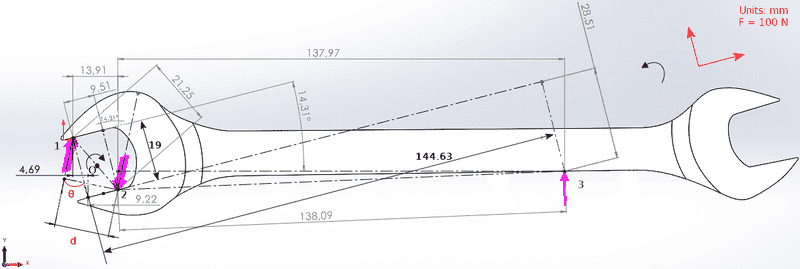
Attachment.png
 
Last edited:
Reply
  • Like
Likes   Reactions: Delta2
Physics news on Phys.org
Welcome to PF.

I think you are modelling the spanner with the force 3 applied up when it should be down. The reason is that the offset head will tend to slide off a nut if used the way you show it here. That would change the hexagonal nut contact points into the diagonally opposite positions between the jaws, which puts them at more similar distances along the handle.

The offset head allows a hexagonal nut in a confined place, to be advanced in 30° steps, by repeatedly turning over the spanner when access is restricted. But it also allows the more secure orientation when working on a more exposed nut.

The two nut edges that contact the spanner jaws will be deformed by the pressure of the spanner until the area of the contact is sufficient to handle the force applied. When you model the hardened spanner jaws, it is the nut that will deform, not the spanner. Maybe you need to model the soft plastic nut between the hard jaws.
 
Reply
  • Like
Likes   Reactions: Lnewqban
Hi,

##M_O = F_1 \cdot d, ~ \text{&} ~ F_1=F_2##
How have you determined that those forces are equal ? And what do you use for ##d## ?

I take it the purple ##O## is the center of the nut ?

Then, if the purple ##O## is your center of rotation, shouldn't the 144.63 (144.93 ?) be smaller ?
Like the 137.97 + 4.69
Now it looks as if it is up to the point where ##F_1## acts

The drawing has a lot of measurements that are unexplained.

And how do you determine these to such an accuracy ?

##\ ##
 
BvU said:
Hi,

How have you determined that those forces are equal ? And what do you use for ##d## ?

I take it the purple ##O## is the center of the nut ?

Then, if the purple ##O## is your center of rotation, shouldn't the 144.63 (144.93 ?) be smaller ?
Like the 137.97 + 4.69
Now it looks as if it is up to the point where ##F_1## acts

The drawing has a lot of measurements that are unexplained.

And how do you determine these to such an accuracy ?

##\ ##
Hello,
I assumed that ##F_1=F_2##.
##d## is the unknown and I want to determine it.
Indeed ##O## is the center of the nut.

##144.93 = 137.97+\frac{13.91}{2}## is the perpendicular distance from point ##O## to point ##3## (Force ##F_3##).

I apologize for the complexity of my drawing. Measurements were taken from the software that I designed this hand tool (with some roundings).