ApostoF
- 4
- 2
- TL;DR
- Question about reasonable simplifications for heat transfer in hot air piccolo tube anti-ice systems
Hi, I'm doing a project on heat transfer using hot air piccolo tubes as an anti-ice system on the inside of an airplane wing. I've been reading as much info as possible using research papers from modern times and all the way back to when NASA was still NACA haha. I am planning to do a 3D analysis on this, but I also want to simplify the problem and see if a simplified 1D, 2D analysis or 3D analysis using finite difference methods in MATLAB would produce decent approximations of what the 3D fluid flow software would obtain.
My question is, how would you simplify this problem so that a simple program like MATLAB could produce anything reasonable? I have some ideas, and am just looking for feedback or other ideas if you have any.
Here is my thinking so far: For simplifying, first of all, I am considering only using the system as an "anti-ice" and not "de-ice" - i.e., I want to keep the temperatures above freezing, instead of having to calculate the latent heats and whatnot needed to melt ice already there. I am only an undergrad so for the purposes of this project, it is definitely sufficient for what I want to do. I am only doing analysis on the leading edge of the wing, not the entire chord width. I am considering only the flows after the hot air jet leaves the piccolo tube for the 2D model. I am not considering pressure drop through the distance lengthwise of the tube, and am assuming this will be taken care of by the decreasing diameter of the piccolo tube.
For the geometry, I am a little confused about what is reasonable to simplify. If it were accurate, obviously the easiest answer would be to model as a plane wall with convection internally from the hot air streams and external convection from the air around the outside. Not sure if I should instead model as flow over a pipe to somewhat simulate an airfoil shape on the leading edge of the wing instead. If I did, I am unsure how I would model the internal convection, since I am only looking at after the hot air jet leaves the tube, really it would be an odd crossflow situation where the hot air jets would be pointed normal to the internal semi-circular shape (inside of the wing). Additionally, I am wondering if the radiation losses on the outside of the wing are actually non-negligible, because my intuition says maybe not.
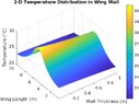
So far what I've done is try to model this as a 2D planar wall, but simulating the hot impinging air jets by having a localized higher convection coefficient where the jets are directly pointed towards, then exponentially decreasing the convection coefficient away from the jet streams so that my model shows much higher temps where they are pointed directly - which agrees with the research papers I've read that have done the 3D analysis. In your opinion, is this reasonable? Is there a better geometry to use here? I have attached an output figure I got from MATLAB (I used the wing thickness as 1m just to see if my code was actually calculating the conduction through the wing, obviously it will be a lot thinner).
Any advice or opinions or criticism (or just telling me I'm in way over my head) is welcome! I know it's a lot to ask, but I really appreciate this forum and figured I might as well try to get some outside opinions from people. Thank you.
My question is, how would you simplify this problem so that a simple program like MATLAB could produce anything reasonable? I have some ideas, and am just looking for feedback or other ideas if you have any.
Here is my thinking so far: For simplifying, first of all, I am considering only using the system as an "anti-ice" and not "de-ice" - i.e., I want to keep the temperatures above freezing, instead of having to calculate the latent heats and whatnot needed to melt ice already there. I am only an undergrad so for the purposes of this project, it is definitely sufficient for what I want to do. I am only doing analysis on the leading edge of the wing, not the entire chord width. I am considering only the flows after the hot air jet leaves the piccolo tube for the 2D model. I am not considering pressure drop through the distance lengthwise of the tube, and am assuming this will be taken care of by the decreasing diameter of the piccolo tube.
For the geometry, I am a little confused about what is reasonable to simplify. If it were accurate, obviously the easiest answer would be to model as a plane wall with convection internally from the hot air streams and external convection from the air around the outside. Not sure if I should instead model as flow over a pipe to somewhat simulate an airfoil shape on the leading edge of the wing instead. If I did, I am unsure how I would model the internal convection, since I am only looking at after the hot air jet leaves the tube, really it would be an odd crossflow situation where the hot air jets would be pointed normal to the internal semi-circular shape (inside of the wing). Additionally, I am wondering if the radiation losses on the outside of the wing are actually non-negligible, because my intuition says maybe not.
So far what I've done is try to model this as a 2D planar wall, but simulating the hot impinging air jets by having a localized higher convection coefficient where the jets are directly pointed towards, then exponentially decreasing the convection coefficient away from the jet streams so that my model shows much higher temps where they are pointed directly - which agrees with the research papers I've read that have done the 3D analysis. In your opinion, is this reasonable? Is there a better geometry to use here? I have attached an output figure I got from MATLAB (I used the wing thickness as 1m just to see if my code was actually calculating the conduction through the wing, obviously it will be a lot thinner).
Any advice or opinions or criticism (or just telling me I'm in way over my head) is welcome! I know it's a lot to ask, but I really appreciate this forum and figured I might as well try to get some outside opinions from people. Thank you.
 not sure if I have a good answer there yet.